Modular multilevel inverters (MMLIs), acknowledged not only for its modular structure, scalability and low harmonic distortion but also offers an efficient solution, for managing high-power renewable-energy applications. However, these often depends on conventional centralized control methods, which are insufficient in addressing critical challenges like scalability and hardware delays in distributed control systems. This paper emphases on the design and implementation of an advanced 3-Ph. MMLI for a 400-kW solar plant connected to a 25 kV grid. The study examines the system's performance, control strategies and operational challenges encountered during the integration with grid. To optimize energy extraction from the PV array, incorporate a DC/DC, converter featuring MPPT, through ‘Perturb and Observe’ (P & D) technique. The extracted energy is then stepped up and converted into 3-Ph. AC voltage through MMLI. The output from these, feed into a common 500V DC bus, enabling the overall system integration. Unlike earlier methods which are used open-loop control to address power imbalances among legs, this study employs closed-loop control using to correct mismatched DC loop currents. This allows, dynamic adjustment the voltage across PV array to optimize output efficiency. The efficacy of the proposed control-strategy has been validated through Mat lab/Simulink simulations, demonstrating its potential.
| Published in | Science Discovery Energy (Volume 1, Issue 1) |
| DOI | 10.11648/j.sdenergy.20260101.11 |
| Page(s) | 1-13 |
| Creative Commons |
This is an Open Access article, distributed under the terms of the Creative Commons Attribution 4.0 International License (http://creativecommons.org/licenses/by/4.0/), which permits unrestricted use, distribution and reproduction in any medium or format, provided the original work is properly cited. |
| Copyright |
Copyright © The Author(s), 2026. Published by Science Publishing Group |
Modular Multilevel Inverter (MMLI), Voltage Sourced Converter (VSC), Distributed Maximum Power Point Tracking (DMPPT), Total Harmonic Distortion (THD).
Parameter | Specifications |
|---|---|
PV Array | Capable of delivering up to 100 kW under peak irradiance conditions (1000 W/m²). |
DC/DC Boost Converter | Operating at 5 kHz, it elevates PV’s natural voltage (273 V DC at peak power) to 500 V DC. The MPPT controller dynamically adjusts duty-cycle to optimize voltage for maximum power extraction. |
Filtering System | 10 KVAR Capacitor-bank diminishes the harmonics generated by VSC |
Coupling Transformer | 100 KVA, 260 V/25 KV, 3-Ph. transformer connects the system to utility grid |
Grid Infrastructure | Includes a 25 KV distribution-feeder & an equivalent 120 KV transmission network |
PV Module Configuration | The system integrates 330 Sun-Power SPR-305E-WHT-D modules arranged in 66 strings each string containing five modules connected in series (66 × 5 × 305.2 W = 100.7 KW) |
Parameter | Specifications |
|---|---|
No. of series-connected cells | 96 |
OC voltage (Voc) | 64.2 V |
SC current (Isc) | 5.96 A |
Max. power point voltage (Vmpt) | 54.7 V |
Max. power point voltage and current (Impt) | 5.58 A |
MMLI | Modular Multilevel Inverter |
MLI | Multilevel Inverter |
MPPT | Maximum Power Point Tracking |
MG | Micro Grid |
VSC | Voltage Sourced Converter, |
DMPPT | Distributed Maximum Power Point Tracking |
THD | Total Harmonic Distortion |
MMGs | Multi-micro Grids |
MMC | Modular Multilevel Converter |
PV | Photovoltaic |
CHB | Cascaded H-Bridge Converters |
P & D | Perturb and Observe |
AC | Alternating Current |
DC | Direct Current |
| [1] | Sharma, B., Manna, S., Saxena, V. et al. “A comprehensive review of multi-level inverters, modulation, and control for grid-interfaced solar PV systems”. Sci Rep 15, 661 (2025), |
| [2] | Jayaraman, R., Thamizharasan, S., Baskaran, J., Meena, V. P., Bahadur, J, Jadoun, V. K, “High efficiency multilevel inverter topology with minimal switching devices for enhanced power quality and reduced losses” (2025)., IET Power Electron. 18, e12851, |
| [3] | R. Tayal, S. P. Bihari, J. Kumar, G. S. Chaurasia and R. Sharma (2024) "Maximum Power Point Tracking in Grid Connected PV System Using APSO," 2024 4th International Conference on Advancement in Electronics & Communication Engineering (AECE), |
| [4] | Ramesh Adireddy, Boddu Sai Deepak, M. Ravindra, K. V. S. Ramachandra Murthy, (2022) “Study of different techniques to mitigate temporary overvoltage in photovoltaic system”, Materials Today: Proceedings, Volume 56, Pages 3222-3226, |
| [5] | Singh, V. Jately, P. Kala, Y. Yang and B. Azzopardi, (2024) "Advancements in Multilevel Inverters for Efficient Harnessing of Renewable Energy: A Comprehensive Review and Application Analysis," in IEEE Access, vol. 12, pp. 156939-156964, |
| [6] | Singh, S., and Singh, S. (2024), "Advancements and Challenges in Integrating Renewable Energy Sources Into Distribution Grid Systems: A Comprehensive Review." ASME. J. Energy Resour. Technol. September 2024; 146(9): 090801. |
| [7] | Abhishek Kumar, Arvind R. Singh, R. Seshu Kumar, Yan Deng, Xiangning He, R. C. Bansal, Praveen Kumar, R. M. Naidoo, (2023) “An effective energy management system for intensified grid-connected microgrids”, Energy Strategy Reviews, Volume 50, 101222, ISSN 2211-467X, |
| [8] | Ahmed Rashwan, Alexey Mikhaylov, Mahmoud Hemeida, Gabor Pinter, Dina S. Osheba, (2023) “Two-stage grid-connected inverter topology with high frequency link transformer for solar PV systems”, Energy Reports, Volume 10, 2023, Pages 1864-1874, |
| [9] | Khodaparast, Aryorad, Erfan Azimi, Ali Azimi, M. Ebrahim Adabi, Jafar Adabi, and Edris Pouresmaeil. 2019. "A New Modular Multilevel Inverter Based on Step-Up Switched-Capacitor Modules" Energies 12, no. 3: 524. |
| [10] | Boucheriette, Wafa & Moussi, Ammar & Mechgoug, Raihane & Hani, Benguesmia. (2023). A Multilevel Inverter for Grid-Connected Photovoltaic Syste Optimized by Genetic Algorithm. Engineering, Technology & Applied Science Research. 13. 10249-10254. |
| [11] | Chandio, R. H., Akhtar Chachar, F., Soomro, J. B., Ansari, J. A., Munir, H. M., Zawbaa, H. M., et al. (2023). Control and protection of MMC-based HVDC systems: a review. Energy Rep. 9, 1571–1588. |
| [12] | C. Jin, Y. Xiao, Q. Jia, H. Ji, Y. Dragicevic, T. Teodorescu, R. Blaabjerg, F (2023). “A Novel Detection and Localization Approach of Open-Circuit Switch Fault for the Grid-Connected Modular Multilevel Converter”, IEEE Trans. Ind. Electron, 70, 112–124. |
| [13] | D. Ravi Kishore, T. Vijay Muni, B. Srinivas Raja, Mukesh Pushkarna, B. Srikanth Goud, Kareem M. AboRas, Sadam Alphonse (2023) “Grid-Connected Solar PV System with Maximum Power Point Tracking and Battery Energy Storage Integrated with Sophisticated Three-Level NPC Inverter”, |
| [14] | Ramesh. A, B. V. S. S. S. Gopal, M. Ravindra, K. V. S. Ramachandra Murthy (2022) “Thirteen and Twenty-one level Hybrid H-Bridge Multilevel Inverter Topology for Grid Connected System”, International Journal of Grid and Distributed Computing, Vol. 13, No. 1, pp. 1794 1804. |
| [15] | Kishor Thakre, Kanungo Barada Mohanty, Vinaya Sagar Kommukuri, Aditi Chatterjee, Prateek Nigam, Sanjeev Kumar Gupta, (2022) “Modified cascaded multilevel inverter for renewable energy systems with less number of unidirectional switches”, Energy Reports, Volume 8, Pages 5296-5304, ISSN 2352-4847, |
| [16] | Liu, C. Deng, F. Zhang, J. Cai, X. Chen, Z. Blaabjerg, F. (2022) Power Loss Reduction Control for Modular Multilevel Converters Based on Resistor Controllable Sub module. IEEE Trans Power Electron. 37, 9767–9776. |
| [17] | Uddin W, Zeb K, Adil Khan M, Ishfaq M, Khan I, Islam Su, Kim H-J, Park GS, Lee C. Control of Output and Circulating Current of Modular Multilevel Converter Using a Sliding Mode Approach. Energies. 2019; 12(21): 4084, |
| [18] | A. A. Taffese, E. de Jong, S. D’Arco and E. Tedeschi, "Online Parameter Adjustment Method for Arm Voltage Estimation of the Modular Multilevel Converter," in IEEE Transactions on Power Electronics, vol. 34, no. 12, pp. 12491-12503, Dec. 2019, |
| [19] | R. Venkedesh, R. AnandhaKumar, G. Renukadevi (2022),”THD reduction in measurement of H - Bridge multilevel inverter using pulse modulated switching integrated with linear quadratic Regulator”, Measurement: Sensors, Volume 24, 100435, |
| [20] | Li, M., Chang, X., Dong, N., Liu, S., Yang, H., and Zhao, R. (2021). Arm-current-based model predictive control for modular multilevel converter under unbalanced grid conditions. IEEE J. Emerg. Sel. Top. Power Electron. 10(3), 3195–3206. |
| [21] | Siddique, M. D., Mekhilef, S., Padmanaban, S., Memon, M. A., Kumar (2020) “Single-phase step-up switched-capacitor-based multilevel inverter topology with SHEPWM” (2021), IEEE Trans. Ind. Appl. 57(3) |
| [22] | S. Wang, G. P. Adam, A. M. Massoud, D. Holliday and B. W. Williams (2019) "Analysis and Assessment of Modular Multilevel Converter Internal Control Schemes," in IEEE Journal of Emerging and Selected Topics in Power Electronics, vol. 8, no. 1, pp. 697-719, March 2020, |
APA Style
Donepudi, T. R., Parasa, K. R., Datta, B. P. S., Chaturvedula, U. P. K., Immanuel, A. (2026). An Advanced Modular Multilevel Inverters for Grid-connected PV Optimization by Maximum Power Point Tracking. Science Discovery Energy, 1(1), 1-13. https://doi.org/10.11648/j.sdenergy.20260101.11
ACS Style
Donepudi, T. R.; Parasa, K. R.; Datta, B. P. S.; Chaturvedula, U. P. K.; Immanuel, A. An Advanced Modular Multilevel Inverters for Grid-connected PV Optimization by Maximum Power Point Tracking. Sci. Discov. Energy 2026, 1(1), 1-13. doi: 10.11648/j.sdenergy.20260101.11
@article{10.11648/j.sdenergy.20260101.11,
  author = {Tata Rao Donepudi and Kondala Rao Parasa and Bhimaraju Pemmanaboidi Srihari Datta and Uma Phanendra Kumar Chaturvedula and Anupalli Immanuel},
  title = {An Advanced Modular Multilevel Inverters for
Grid-connected PV Optimization by Maximum Power Point Tracking},
  journal = {Science Discovery Energy},
  volume = {1},
  number = {1},
  pages = {1-13},
  doi = {10.11648/j.sdenergy.20260101.11},
  url = {https://doi.org/10.11648/j.sdenergy.20260101.11},
  eprint = {https://article.sciencepublishinggroup.com/pdf/10.11648.j.sdenergy.20260101.11},
  abstract = {Modular multilevel inverters (MMLIs), acknowledged not only for its modular structure, scalability and low harmonic distortion but also offers an efficient solution, for managing high-power renewable-energy applications. However, these often depends on conventional centralized control methods, which are insufficient in addressing critical challenges like scalability and hardware delays in distributed control systems. This paper emphases on the design and implementation of an advanced 3-Ph. MMLI for a 400-kW solar plant connected to a 25 kV grid. The study examines the system's performance, control strategies and operational challenges encountered during the integration with grid. To optimize energy extraction from the PV array, incorporate a DC/DC, converter featuring MPPT, through ‘Perturb and Observe’ (P & D) technique. The extracted energy is then stepped up and converted into 3-Ph. AC voltage through MMLI. The output from these, feed into a common 500V DC bus, enabling the overall system integration. Unlike earlier methods which are used open-loop control to address power imbalances among legs, this study employs closed-loop control using to correct mismatched DC loop currents. This allows, dynamic adjustment the voltage across PV array to optimize output efficiency. The efficacy of the proposed control-strategy has been validated through Mat lab/Simulink simulations, demonstrating its potential.},
 year = {2026}
}
TY  - JOUR
T1  - An Advanced Modular Multilevel Inverters for
Grid-connected PV Optimization by Maximum Power Point Tracking
AU  - Tata Rao Donepudi
AU  - Kondala Rao Parasa
AU  - Bhimaraju Pemmanaboidi Srihari Datta
AU  - Uma Phanendra Kumar Chaturvedula
AU  - Anupalli Immanuel
Y1  - 2026/02/25
PY  - 2026
N1  - https://doi.org/10.11648/j.sdenergy.20260101.11
DO  - 10.11648/j.sdenergy.20260101.11
T2  - Science Discovery Energy
JF  - Science Discovery Energy
JO  - Science Discovery Energy
SP  - 1
EP  - 13
PB  - Science Publishing Group
UR  - https://doi.org/10.11648/j.sdenergy.20260101.11
AB  - Modular multilevel inverters (MMLIs), acknowledged not only for its modular structure, scalability and low harmonic distortion but also offers an efficient solution, for managing high-power renewable-energy applications. However, these often depends on conventional centralized control methods, which are insufficient in addressing critical challenges like scalability and hardware delays in distributed control systems. This paper emphases on the design and implementation of an advanced 3-Ph. MMLI for a 400-kW solar plant connected to a 25 kV grid. The study examines the system's performance, control strategies and operational challenges encountered during the integration with grid. To optimize energy extraction from the PV array, incorporate a DC/DC, converter featuring MPPT, through ‘Perturb and Observe’ (P & D) technique. The extracted energy is then stepped up and converted into 3-Ph. AC voltage through MMLI. The output from these, feed into a common 500V DC bus, enabling the overall system integration. Unlike earlier methods which are used open-loop control to address power imbalances among legs, this study employs closed-loop control using to correct mismatched DC loop currents. This allows, dynamic adjustment the voltage across PV array to optimize output efficiency. The efficacy of the proposed control-strategy has been validated through Mat lab/Simulink simulations, demonstrating its potential.
VL  - 1
IS  - 1
ER  -
Department of Electrical and Electronics Engineering, Aditya University, Surampalem, India
Biography: Tata Rao Donepudi, working as Assistant Professor in the Department of Electrical and Electronics Engineering in Aditya University, Surampalem, Andhra Pradesh, India. His Research areas include Power Systems, Power Electronics and Electrical Vehicles. He has two years of Industrial experience and more than twenty years of teaching experience and two years industrial experience He has published various research papers in national and international journals and conferences. He is a member of ISTE, IETE and IAENG.

Department of Electrical and Electronics Engineering, Aditya University, Surampalem, India
Biography: Kondala Rao Parasa, designated as Assistant Professor in the Department of Electrical and Electronics Engineering in Aditya University, Surampalem, Andhra Pradesh. His research areas include power system operation & Control Systems and Electrical Power Distribution systems. He has more than ten 10 years teaching experience and published various research papers in national and international journals and conferences. He is a member of IETE and IAENG.

Department of Electrical and Electronics Engineering, Aditya University, Surampalem, India
Biography: Bhimaraju Pemmanaboidi Srihari Datta, working as an Assistant Professor in the Department of Electrical and Electronics Engineering, Aditya University, Surampalem, Andhra Pradesh, India. His research interests are Power Quality, Electric Vehicles and Smart Grids. He has more than 15 years teaching experience and published various research papers in national and international journals and conferences. He is a member of IAENG and IETE.

Department of Electrical and Electronics Engineering, Aditya University, Surampalem, India
Biography: Uma Phanendra Kumar Chaturvedula, an accomplished academic and a dedicated Assistant Professor in the Department of Electrical and Electronics Engineering in Aditya University, Surampalem, Andhra Pradesh. His research interests include in the cutting-edge areas of smart grids, Power System Optimization, and Electrical Power Distribution systems. He served as a reviewer for several esteemed international journals and conferences. He is a member of ISTE, IETE and IAENG. His enduring contributions continue to inspire and influence the field of Electrical and Electronics Engineering.

Department of Electrical and Electronics Engineering, Gayathri Institute of Technology and Management, Hyderabad, India
Biography: Anupalli Immanuel, an academician, researcher, and innovator in Electrical and Electronics Engineering. He received his B. Tech., M. Tech., and Ph. D. in Electrical and Electronics Engineering from Sri Venkteswara University, Tirupati. With over 18 years of academic and research experience, he has secured research funding from DST-SEED, Atal Innovation Mission, NITI Aayog, and MSME, Government of India. He has authored 30 research publications in reputed international journals and conferences, authored two books, holds two patents, and supervising Seven doctoral scholars. He is frequently invited to deliver lectures on fuzzy logic & Neural Networks, Innovation, Incubation & startups, research methodology, technical writing, and Electric Vehicles. His international exposure includes visits to Hong Kong (2014) and Germany (2019). A professional member of IEEE and Student Branch Counsellor at ASCET, his research interests span power systems, control systems, fuzzy logic, optimization, electric vehicles.

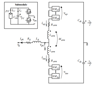
Figure 1. Topology of 1-Phase MMC with PV-modules embedded in each sub-module.
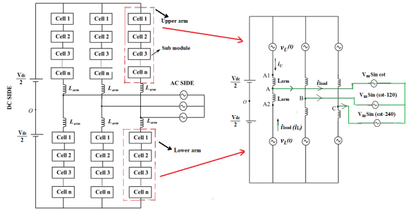
Figure 2. Schematic of 3-pase MMLI topology.
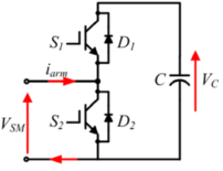
Figure 3. Sub model of MMLI.
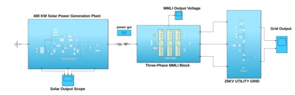
Figure 4. Mat lab/Simulink model of a 400-KW Solar-Power Plant connected to a 25-kV grid using 3-Phase Modular Multi-Level Inverter.
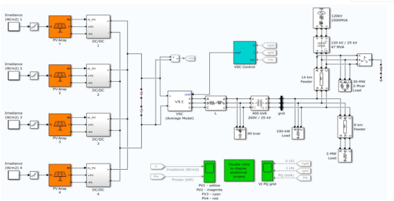
Figure 5. Mat lab/Simulink model of 400 KW solar farm.
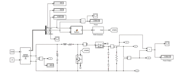
Figure 6. Mat lab/ Simulink model of Equivalent circuit model of 400 KW solar farm.
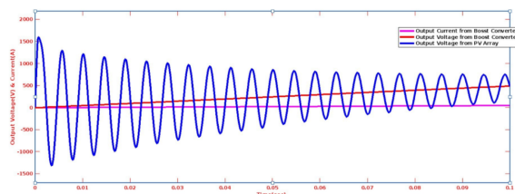
Figure 7. Out-put Voltage and Current of DC/DC boost converter from PV array DC-DC boost-converter.
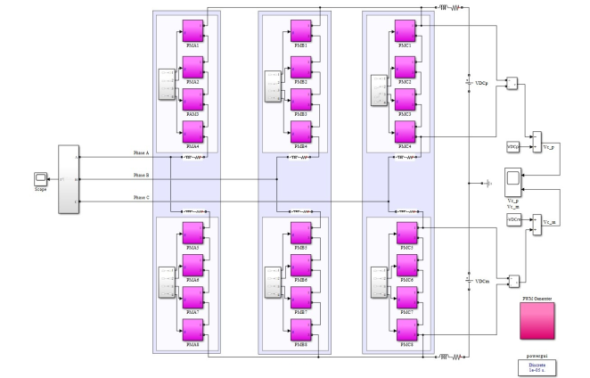
Figure 8. Schematic of Three-Phase MMLI.
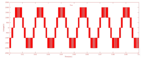
Figure 9. Output voltage of upper part of converter.
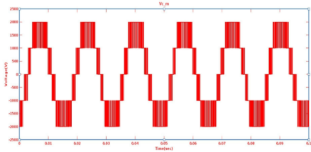
Figure 10. Output voltage of lower part of converter.
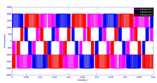
Figure 11. Output voltage of 3-Phase MMLI.
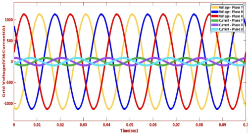
Figure 12. Utility grid Output voltage and current.
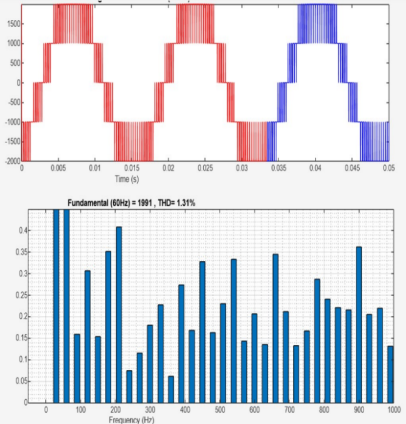
Figure 13. FFT window for output voltage.
Information