1. Introduction
A 3-hinged stiff girder cable is a structural system consisting of a rigid girder with hinged connections at both ends. This configuration provides flexibility and allows for controlled movement at the hinges. Characteristics include three points of support two hinges and one central support offering stability while accommodating structural deformations. One of the earliest instances is the creation of suspension bridges in ancient China, where simple cable structures were employed to traverse rivers and valleys. The iconic design of these bridges evolved over time, with innovations like the introduction of iron cables in the 19th century, exemplified by Thomas Telford's Menai Suspension Bridge in 1826. In the 20th century, the development of high-strength materials such as steel and advancements in cable construction techniques led to the construction of iconic structures like the Golden Gate Bridge in San Francisco (1937) and the Akashi Kaikyo Bridge in Japan (1998), showcasing the evolution of suspended cable systems over the years
| [1] | Gazzola, F. (2015). Brief History of Suspension Bridges. In: Mathematical Models for Suspension Bridges. MS&A, vol 15. Springer, Cham. https://doi.org/10.1007/978-3-319-15434-3_1 |
| [2] | Kahlow, A. (1991). Knowledge Transfer in the Nineteenth Century: Young, Navier, Roebling, and the Brooklyn Bridge. In: Woodward, W. R., Cohen, R. S. (eds) World Views and Scientific Discipline Formation. Boston Studies in the Philosophy of Science, vol 134. Springer, Dordrecht. https://doi.org/10.1007/978-94-011-3164-3_35 |
[1, 2]
. The 3-hinged stiff girder cable systems are commonly used in civil engineering structures such as bridges and canopies. These systems consist of a primary girder supported by hinged connections at each end, with suspenders extending from the girder to a cable or supporting structure above. The suspenders play a significant role in distributing loads from the girder to the supporting structure and ensuring stability and equilibrium of the system
| [3] | Nascimento, F. A. F., Nonato, C. A., Ramos, A. J. A. et al. (2025). Decay rates for Timoshenko beam system with suspenders and arbitrary nonlinear localized damping. Acta Mech. https://doi.org/10.1007/s00707-024-04202-8 |
[3]
. Engagement in the Comparative Analysis of Equivalent UDL Transmitted from 3-Hinged Stiff Girder Cable with Varying Numbers of Suspender because the analysis seeks to quantify and understand the impact of different suspender configurations on load distribution, providing valuable insights that can further enhance the overall design and performance of these cable systems.
The general objective of this study is to compare the theoretical idealization of uniformly distributed load (UDL) transmission with the actual behaviour when varying the number of suspenders in a 3-hinged stiffening girder. To achieve this, specific objectives include conducting a comprehensive comparative analysis of equivalent UDL transmission under point loads and uniformly distributed loads to understand their respective effects on the girder. Furthermore, the study investigates the impact of varying the number of suspenders on load distribution within the cable system to assess how this variation influences structural efficiency. It also examines different suspender configurations to evaluate their role in enhancing the overall structural performance. Additionally, the research explores the variation in tension within the suspenders as a function of their distance from the mid-point of the girder and the location of the applied load, providing insights into the load transfer mechanism and helping optimize the suspension system design.
This section provides an exploration of pivotal methodologies proposed in the existing literature, delving into the inception, analysis, and prospective evolution of the 3-Hinged Stiff Girder. Zhao et al.
performed an experimental study to assess the live load distribution in cable-stayed bridges with different suspender configurations. Through field tests conducted on an actual bridge structure, the researchers measured the distribution of live loads on the bridge deck under varying loading conditions. The experimental results provided valuable empirical data to validate theoretical predictions and numerical simulations, confirming the impact of suspender arrangement on load distribution efficiency
. Shao et al.
conducted a comprehensive parametric analysis to investigate the load-sharing behaviour between the main girder and suspenders in cable-stayed bridges. By varying structural parameters such as girder stiffness, cable properties, and suspension system configuration, the study aimed to identify optimal design parameters that enhance load distribution efficiency
| [7] | Arruda, M. R. T., Serafim, J. P. M. (2017). Parametric test for the preliminary design of suspension bridges. Int J Adv Struct Eng, 9, 165–176. https://doi.org/10.1007/s40091-017-0156-y |
| [8] | Arellano, H., Tolentino, D., Gómez, R. (2019). Optimum Criss Crossing Cables in Multi-span Cable-stayed Bridges using Genetic Algorithms. KSCE J Civ Eng, 23, 719–728. https://doi.org/10.1007/s12205-018-5736-2 |
[7, 8]
. Through numerical simulations and analytical modelling & provided insights into the complex interaction between the main girder and suspenders, highlighting the importance of structural optimization for achieving balanced load distribution
. Shao et al.
| [9] | Shao, F., Chen, Z., & Ge, H. (2020). Parametric analysis of the dynamic characteristics of a long-span three-tower self-anchored suspension bridge with a composite girder. ABEN, 1(10). https://doi.org/10.1186/s43251-020-00010-x |
[9]
conducted a dynamic analysis of cable-stayed bridges with different suspender configurations using the finite element method. The study likely examines factors such as vibration characteristics, natural frequencies, and dynamic stability, providing valuable insights into the design and performance of cable-stayed bridges with different suspender arrangements. This literature review was undertaken to gather insights from recent studies focusing on cable-stayed bridges and their suspender configurations. Each study offers valuable contributions to understanding different aspects of these bridges, including dead & live load distribution, load-sharing behaviour between the main girder and suspenders, static and dynamic analysis
. By synthesizing findings from these studies, it can gain a comprehensive understanding of the factors influencing the performance and design optimization of cable-stayed bridges, particularly regarding suspender configurations and load distribution efficiency
| [10] | Ma, Yuan, Chaolin Song, Zhipeng Wang, Zuqian Jiang, Bin Sun, and Rucheng Xiao. (2024). Efficient Design Optimization of Cable-Stayed Bridges: A Two-Layer Framework with Surrogate-Model-Assisted Prediction of Optimum Cable Forces. Appl. Sci., 14(5), 2007. https://doi.org/10.3390/app14052007 |
[10]
.
2. Methodology
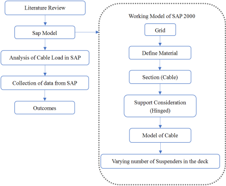
In this comparative analysis, the behaviour of a 3-hinged stiff girder cable under point load & Equivalent Uniformly Distributed Load (UDL) is simulated using SAP2000 software. The focus is on investigating how varying numbers of suspenders affect the distribution of the UDL along the cable, with a practical application perspective. To conduct the simulation, a 3-hinged stiff girder cable model is created within the SAP2000 environment. The model is then subjected to Equivalent UDL under different suspender configurations. The suspender configurations may vary in terms of the number of suspenders employed and their positioning along the cable. During simulation, data is collected to capture various parameters such as deflection, stress distribution, and load sharing among the suspenders. This data serves as the basis for analysing how the number of suspenders influences the distribution of Equivalent UDL along the cable. After collecting the simulation data, thorough analysis is performed to draw conclusions regarding the impact of suspender configuration on load distribution efficiency. Comparative graphs and charts are generated to visually represent the variations in load distribution under different suspender configurations. These visual representations aid in better understanding the differences in behaviour and performance resulting from varying numbers of suspenders. Overall, this comparative analysis provides valuable insights into the structural response of 3-hinged stiff girder cables under Equivalent UDL, considering practical applications. The findings contribute to optimizing suspender configurations for enhanced load distribution efficiency, thereby informing the design and engineering of cable-supported structures.
Figure 1. Flowchart of Modelling.
2.1. Suspended Cable Systems
Suspended cable systems are structural configurations that rely on cables to support loads. These systems are prevalent in various engineering applications, including bridges, transmission towers, and architectural structures. The primary components of suspended cable systems include cables, anchors, and suspenders. Cables are tensioned elements that carry the loads, while suspenders connect the cables to the main structure, facilitating load distribution. The geometry and arrangement of these components determine the overall stability and performance of the system.
2.2. Modelling the External Load As UDL
Mathematically, a UDL is often represented by a linear function, where the intensity of the load per unit length remains constant. For instance, if the total load applied is W and the length of the cable is L, then the UDL intensity w is calculated as w = W/L (assuming uniform distribution). Theoretical considerations of UDL on suspended cables involve analysing how this distributed load interacts with the cable's geometry and material properties. This analysis encompasses aspects such as tension, compression, and bending moments, all of which influence both the sag of the cable and the overall structural equilibrium. In summary, modelling an external load as a UDL entails treating the load as uniformly distributed along the length of the cable, with its intensity remaining constant, and then analysing its effects on the cable's structural behaviour, including tension, compression, bending moments, and equilibrium considerations.
2.3. Suspender Configuration
Suspenders in a cable system connect the cable to the main structure, influencing how loads are transmitted. They contribute to the overall stability and load-sharing capacity of the system. The placement and configuration of suspenders impact the distribution of forces, helping to mitigate stress concentrations and ensuring uniform load transmission.
2.4. Role of the Number of Suspenders
The number of suspenders plays a crucial role in altering load distribution. Increasing or decreasing the number of suspenders affects how the load is distributed along the cable, potentially influencing the structural efficiency and stability of the system. The optimization of the number of suspenders is essential for achieving a balance between structural performance, material usage, and construction complexity.
2.5. Importance of Understanding Load Distribution in 3-Hinged Stiff Girder Cables
In 3-hinged stiff girder cables, load distribution is a critical aspect that influences the structural integrity and efficiency of the system. These structures typically consist of a rigid girder with hinged connections at both ends, providing flexibility. Understanding how loads are distributed along the length of the cable is essential for ensuring that the structure can withstand applied forces without compromising safety or stability. Proper load distribution analysis allows engineers to optimize the design of 3-hinged stiff girder cables, ensuring that the materials are utilized efficiently and that the structure can accommodate various loading conditions. It also aids in identifying potential stress concentrations or weak points in the system, guiding engineers in implementing appropriate reinforcement measures.
2.6. Significance of the Number of Suspenders in Influencing Structural Behaviour
The number of suspenders in a suspended cable system plays a crucial role in determining its structural behaviour. Suspenders serve to connect the cables to the main structure, and their placement and quantity impact how the loads are transmitted. By varying the number of suspenders, engineers can influence the distribution of forces within the cable system. The significance lies in achieving an optimal balance between load-bearing capacity, stability, and material efficiency. An insufficient number of suspenders may lead to uneven load distribution, potentially causing localized stress concentrations or overloading certain elements. On the other hand, an excessive number of suspenders may result in unnecessary complexity and increased construction costs without proportional benefits in load distribution. Understanding the influence of the number of suspenders on structural behaviour is essential for designing cost-effective and resilient suspended cable systems. It allows engineers to tailor the configuration to specific project requirements, ensuring that the structure can efficiently support applied loads while maintaining stability and safety.
2.7. Structural Components Used
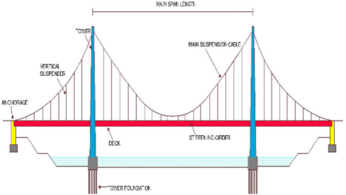
The basic structural components of a suspension bridge system are shown in
Figure 2.
1). Main Cables: These are the primary load-bearing cables that support the bridge deck. In a self-anchored suspension bridge, these cables are looped around the tops of the bridge towers, and their ends are not anchored to the ground.
2). Bridge Towers: These are vertical structures that support the main cables and help distribute the load of the bridge. In a self-anchored suspension bridge, the main cables pass over the tops of the towers and are secured in a loop, eliminating the need for traditional anchorages.
3). Bridge Deck: The deck is the part of the bridge that carries the traffic, pedestrians, or other loads. It is suspended from the main cables and can vary in design depending on the specific requirements of the bridge.
4). Suspender Cables: These cables connect the main cables to the bridge deck, providing vertical support. The number and arrangement of suspender cables depend on the bridge's design and specifications.
5). Foundation: The bridge towers and, if applicable, the anchorages for the main cables are supported by foundations. The foundations are crucial for providing stability and transmitting the load of the bridge to the ground.
Figure 2. Suspension cable with its components.
6). Anchorages (Optional): While traditional suspension bridges have anchorages on the ground to secure the ends of the main cables, a self-anchored suspension bridge eliminates the need for such anchorages. Instead, the main cables form a closed loop around the bridge towers.
2.8. Classical Theories for Analysis
The stiffening girder is horizontal and straight. The geometric moment of inertia is constant. The dead load of the stiffening girder and the cables is uniform. The coordinates of the cable are parabolic. The cable is completely flexible and all dead loads are taken into the cables. The elastic theory did not account for stiffening effect for the main cable under tension, thus gave higher moments in the stiffening girder, thus the live load moment produced in girder is reduced by the horizontal component of live load tension in the cable. The economy of construction offered by deflection theory made this theory absolute.
2.9. Deflection Theory
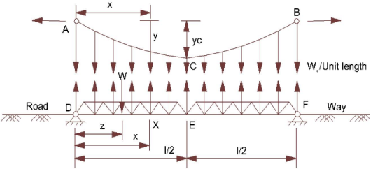
The deflection theory is an extension of elastic theory. The bending moment, M(x) of the stiffening girder after the loading the live load is shown in equation &
Figure 3.
Where,
bending moment resulting from the live load applied to a simple beam of the same span length as the stiffening girder
= longitudinal position of the cable
= deflection of the cable and the stiffening girder due to live load
, = cable horizontal tension due to dead load and live load
Figure 3. Deflection Theory with UDL over whole span.
2.10. Analysis of Static Behaviour
The static behaviour of the cable refers to its response under the influence of an Equivalent Uniform Distributed Load (UDL) varying the number of suspenders in a 3-hinged stiff girder cable system impacts how the cable statically reacts to the applied load. Suspenders play a crucial role in distributing the Equivalent UDL along the length of the cable. The number of suspenders influences how the load is transmitted, affecting the balance of forces within the cable system. The static equilibrium of the cable is crucial, and different suspender configurations can alter the distribution of forces, affecting the overall stability of the system. Optimizing the number of suspenders aims to achieve a state where the cable remains in static equilibrium under the applied Equivalent UDL. The static behaviour analysis evaluates the efficiency of the cable structure in supporting the load while maintaining stability. The goal is to find an optimal suspender configuration that minimizes stress concentrations, ensures uniform load distribution, and enhances the structural efficiency of the 3-hinged stiff girder cable system.
3. Result and Findings
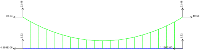
Applying the equivalent UDL to the girder within each model and observe in
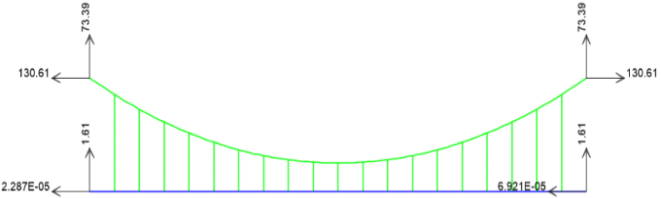
Figure 4 how the load is transmitted through the system for each configuration of suspenders & ensuring that the loading conditions are consistent across all models.
Figure 4. Reactions Under Uniformly Distributed Load (UDL) Analyzed Using SAP.
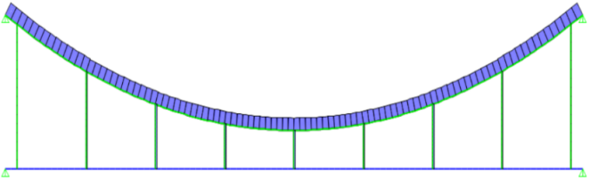
Figure 5. Model of Suspension cable in SAP.
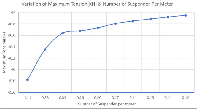
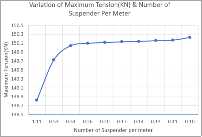
Figure 6. Variation of the maximum tension and number of suspenders per meter in UDL.
Figure 7. Variation of the number of suspender and maximum tension in point load.
Table 1. Result of UDL Configuration.
Number of Suspender | Maximum Tension (KN) | Number of Suspender Per Meter |
9 | 45.821 | 1.111 |
19 | 46.353 | 0.526 |
29 | 46.637 | 0.345 |
39 | 46.678 | 0.256 |
49 | 46.730 | 0.204 |
59 | 46.806 | 0.169 |
69 | 46.850 | 0.145 |
79 | 46.886 | 0.127 |
89 | 46.919 | 0.112 |
99 | 46.950 | 0.101 |
In each model, a point load is applied at two specific locations: 2.5 meters and 7.5 meters from the left end of the cable to the girder. This loading condition is maintained consistently across all configurations of suspenders. By observing
Figure 8 how the load is transmitted through the system for each variation of suspender configuration, it can assess the structural response and evaluate the effectiveness of different configurations in distributing and managing the applied loads.
Figure 8. Reactions having point load at 2.5m & 7.5m from left support in SAP.
Table 2. Result of Point load Configuration.
Number of Suspender | Maximum Tension (KN) | Number of Suspender Per Meter |
9 | 148.817 | 1.11 |
19 | 149.721 | 0.53 |
29 | 150.043 | 0.34 |
39 | 150.096 | 0.26 |
49 | 150.115 | 0.20 |
59 | 150.130 | 0.17 |
69 | 150.140 | 0.14 |
79 | 150.155 | 0.13 |
89 | 150.168 | 0.11 |
99 | 150.230 | 0.10 |
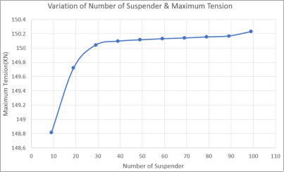
Figure 9. Variation of Maximum Tension with Number of Suspenders Under Point Load.
Figure 10. Variation of the maximum tension & number of suspenders per meter in point load.
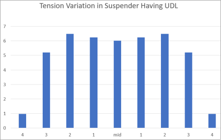
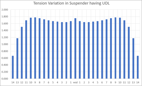
Figure 11. Tension Variation Along the Cable Span with 9 Suspenders UDL.
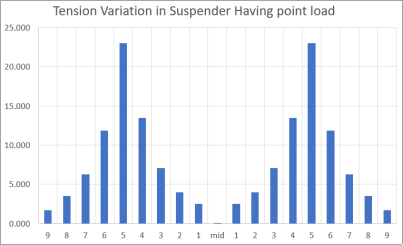
Figure 12. Tension Variation Along the Cable Span with 9 Suspenders Under Point Load.
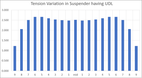
Figure 13. Tension Variation Along the Cable Span with 18 Suspenders under UDL.
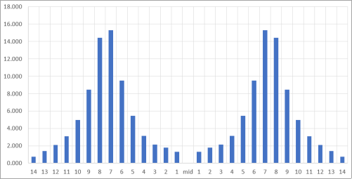
Figure 14. Tension Variation Along the Cable Span with 18 Suspenders under under point load.
Figure 15. Tension Variation Along the Cable Span with 29 Suspenders Under UDL.
Figure 16. Tension Variation Along the Cable Span with 29 Suspenders Under pont load.
Figure 17. Tension Variation Along the Cable Span with 39 Suspenders Under UDL.
Figure 18. Tension Variation Along the Cable Span with 39 Suspenders Under pont load.
Figure 19. Tension Variation Along the Cable Span with 49 Suspenders Under UDL.
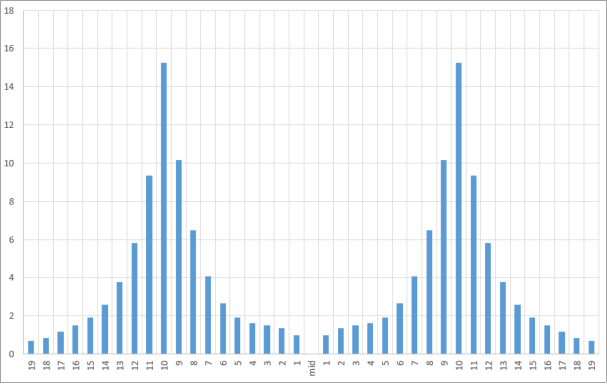
Figure 20. Tension Variation Along the Cable Span with 49 Suspenders Under point load.
The
Figures 11, 13, 15, 17 & 19 shows tension variation in a suspension cable under a uniform load is highest where the load is most concentrated and decreases gradually as it move away from load point as shown in
Figures 12, 14, 16, 18 & 20 reflecting the redistribution of forces along the cable. The tension variation in a suspension cable is greater near a point load due to the concentrated force it applies, and it gradually decreases as it move away from the load location, reflecting the redistribution of forces along the cable. Our findings reveal that the number of suspenders has a significant impact on the distribution of load along the length of the cable. Specifically, as the number of suspenders increases, the load is more evenly distributed, resulting in a reduction in the maximum stress experienced by the cable and the supporting structure. This suggests that increasing the number of suspenders can potentially improve the structural efficiency and stability of the system.
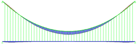
Figure 21. Axial Forces Experienced by the Cable Under UDL.
The tension in a suspension cable varies significantly under the influence of a uniformly distributed load. As the load is spread out along the cable, the tension is highest where the load is most concentrated and decreases gradually as we move away from this point. When a uniform load is applied to a suspension cable, it creates a consistent force distributed along the length of the cable. However, due to the nature of the cable's structure and material, the tension is highest where the load is most concentrated. As we move away from this concentrated point, the force exerted on the cable gradually decreases, resulting in a reduction in tension as shown in
Figure 21.
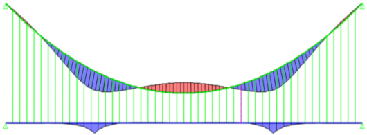
Figure 22. Axial Forces Experienced by the Cable Under point load.
The tension in a suspension cable varies significantly where a point load is applied, and it decreases as the distance from the point load increases. This phenomenon can be explained by considering the distribution of forces along the cable. When a point load is placed on a suspension cable, it creates a concentrated force at that specific location. This force causes the cable to stretch and increases the tension in the immediate vicinity of the load. As it move away from the point load, the force exerted on the cable decreases, resulting in a reduction in tension. This decrease in tension with distance from the point load can be attributed to the redistribution of forces within the cable. As the distance increases, the influence of the point load diminishes, and the cable returns to a more uniform distribution of tension. At points where external loads are applied, such as at the towers or anchorages, bending moments are typically highest due to the concentrated forces acting at these locations. As it move away from these points of load application, the bending moments typically decrease, assuming the load distribution is uniform along the cable's length as shown in
Figure 22. However, it's important to note that the distribution of bending moments in a suspension cable is not always uniform. Factors such as cable sag, variations in cable stiffness, and the interaction between the cable and the suspended structure can lead to complex distributions of bending moments along the cable's length.
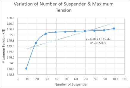
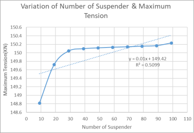
The relationship between the number of suspenders and the maximum tension was evaluated, as depicted in
Figure 23. The graph demonstrates that increasing the number of suspenders initially results in a significant increase in the maximum tension, which then stabilizes. The best-fit curve for this relationship is a linear regression with the equation:
y = 0.01x + 149.42, R² = 0.5099
This indicates a moderate correlation between the variables, as the value of R² suggests that approximately 50.99% of the variation in the maximum tension can be explained by the number of suspenders.
Figure 23. Variation of Number of Suspender and Maximum Tension.
Similarly,
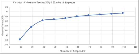
Figure 24 explores the relationship between the maximum tension (in kN) and the number of suspenders. A steady increase in maximum tension is observed with an increasing number of suspenders. The best-fit linear regression for this dataset is given by the equation:
y = 0.0097x + 46.141, R² = 0.7258
This equation represents a stronger correlation compared to the previous figure, with R² = 0.7258 indicating that 72.58% of the variation is explained by the independent variable.
Figure 24. Variation of Maximum Tension (kN) and Number of Suspender.
4. Conclusion
The comparative analysis conducted on the equivalent UDL transmitted from a 3-hinged stiffening girder cable by varying the number of suspenders has provided valuable insights into the structural behaviour of such systems. Through comprehensive simulations and calculations, several key observations have been made:
1). When comparing a 3-hinged stiff girder under point load and uniformly distributed loads, it was observed that the number of suspenders has a significant impact on the distribution of the UDL along the length of the cable. As the number of suspenders increases, the load distribution becomes more uniform, leading to a more balanced structural response as there is 4-5% error between Manual value & Sap value. There's a noticeable gap between theoretical and SAP-based tension values when point loads are applied SAP results differ by about 2-3% from theoretical predictions.
2). The number of suspenders in a suspension bridge significantly influences load distribution. As the number of suspenders increases, the load distribution becomes more uniform, reducing localized stress on the cables and girder. This leads to a more balanced structural performance, minimizing the risk of overstressing individual components.
3). Variations in suspender configurations, such as their spacing affect the overall structural stability and stress distribution. Optimized configurations tend to distribute loads more evenly and enhance structural integrity. Configurations with wider spacing between suspenders may require additional reinforcement in the girder due to increased localized stress.
4). The tension in suspenders varies with distance from the midpoint of the girder and the point of application of the load. Suspenders near the load point experience higher tension, while those farther away tend to carry less load.
5). Increasing the number of suspenders improves maximum tension, with a moderate correlation initially and a stronger correlation as tension variations stabilize.
Author Contributions
Bandana Shah: Conceptualization, Data curation, Formal Analysis, Methodology, Software
Bishek Maharjan: Data curation, Software, Project Administration, Formal Analysis
Khem Raj Regmi: Funding acquisition, Project administration, Resources, Visualization
Ajay Yadav: Conceptualization, Data curation, Formal Analysis, Methodology, Project administration, Software, Supervision, Validation, Visualization, Writing - Origional draft, Writing- review & editing
Ashvin Oli: Conceptualization, Data curation, Formal Analysis, Methodology, Software, Visualization