
Foundations are important in structural engineering, as they transfer loads to the ground. It is challenging to design combined footings on uneven ground due to load eccentricity, soil heterogeneity, and material efficiency. Traditional methods, based on oversimplified assumptions of soil pressure, fail. This paper introduces a new model for optimal multigonal corner combined footing design, with minimum size but with the capacity to adapt to varying loads and soil strengths. The model offers flexible footing slopes (90° to 0°) to place the load and geometric centers, offering uniform stress distribution and preventing eccentric loading. Optimized in Python for numerical accuracy and Maple for symbolic calculation, the model is computed using numerical analysis. The result is better regions of footing, with lower b1 and b2 in end columns, and greater n and m, which enhance stress distribution and lessen load eccentricity. The model is recommended for the design of corner combined footings with four continuous lines of property. Practical recommendations and future research for smaller dimensions and column spacing effects on footing design finalize the paper.
| Published in | Mathematical Modelling and Applications (Volume 11, Issue 3) |
| DOI | 10.11648/j.mma.20261103.12 |
| Page(s) | 70-89 |
| Creative Commons |
This is an Open Access article, distributed under the terms of the Creative Commons Attribution 4.0 International License (http://creativecommons.org/licenses/by/4.0/), which permits unrestricted use, distribution and reproduction in any medium or format, provided the original work is properly cited. |
| Copyright |
Copyright © The Author(s), 2026. Published by Science Publishing Group |
Footing Optimization, Multigonal Corner Combined Footings, Mathematical Modeling, Python and Maple
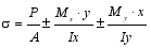 (1)
Type | Loads of column 1 | Loads of column 2 | Loads of column 3 | Load center | |||||||
|---|---|---|---|---|---|---|---|---|---|---|---|
P1 kN | Mx1 kN-m | My1 kN-m | P2 kN | Mx2 kN-m | My2 kN-m | P3 kN | Mx3 kN-m | My3 kN-m | X(m) | Y(m) | |
1 | 700 | 200 | 150 | 1200 | 250 | 350 | 1000 | 300 | 300 | 2.20 | 1.67 |
2 | 700 | -200 | 150 | 1200 | -250 | 350 | 1000 | -300 | 300 | 2.20 | 2.18 |
3 | 700 | 200 | -150 | 1200 | 250 | -350 | 1000 | 300 | -300 | 2.75 | 1.67 |
4 | 700 | -200 | -150 | 1200 | -250 | -350 | 1000 | -300 | -300 | 2.75 | 2.18 |
Type | Loads of column 1 | Loads of column 2 | Loads of column 3 | Load center | |||||||
|---|---|---|---|---|---|---|---|---|---|---|---|
P1 kN | Mx1 kN-m | My1 kN-m | P2 kN | Mx2 kN-m | My2 kN-m | P3 kN | Mx3 kN-m | My3 kN-m | X(m) | Y(m) | |
1 | 1200 | 200 | 150 | 800 | 250 | 350 | 900 | 300 | 300 | 1.44 | 1.53 |
2 | 1200 | -200 | 150 | 800 | -250 | 350 | 900 | -300 | 300 | 1.44 | 1.98 |
3 | 1200 | 200 | -150 | 800 | 250 | -350 | 900 | 300 | -300 | 1.99 | 1.53 |
4 | 1200 | -200 | -150 | 800 | -250 | -350 | 900 | -300 | -300 | 1.99 | 1.98 |
Type | Sum of loads and moments | Optimal area (m2) | Dimension of the footing(m) | Struss generated by loads in each corned(kN/m2) | Geometric center | |||||||||||||
|---|---|---|---|---|---|---|---|---|---|---|---|---|---|---|---|---|---|---|
FR kN | MxT kN-m | MyT kN-m | At | a | b | b1 | b2 | n | m | σ1 | σ2 | σ3 | σ4 | σ5 | σ6 | X(m) | Y(m) | |
σall=200.00 kN/m2 | ||||||||||||||||||
1 | 2900 | 0.00 | 0.00 | 14.50 | 7.17 | 6.65 | 0.26 | 0.61 | 0.11 | 2.55 | 200.00 | 200.00 | 200.00 | 200.00 | 200.00 | 200.00 | 2.20 | 1.67 |
2 | 2900 | 0.00 | 0.00 | 14.50 | 7.17 | 10.27 | 0.57 | 0.43 | 0.05 | 1.80 | 200.00 | 200.00 | 200.00 | 200.00 | 200.00 | 200.00 | 2.20 | 2.18 |
3 | 2900 | 0.00 | 0.00 | 14.50 | 9.82 | 6.81 | 0.28 | 0.77 | 0.134 | 1.39 | 200.00 | 200.00 | 200.00 | 200.00 | 200.00 | 200.00 | 2.75 | 1.67 |
4 | 2900 | 0.00 | 0.00 | 14.50 | 10.13 | 10.24 | 0.26 | 0.49 | 0.05 | 1.40 | 200.00 | 200.00 | 200.00 | 200.00 | 200.00 | 200.00 | 2.75 | 2.18 |
σall=250.00 kN/m2 | ||||||||||||||||||
1 | 2900 | 0.00 | 0.00 | 11.60 | 7.75 | 7.68 | 0.32 | 0.43 | 0.12 | 1.56 | 250.00 | 250.00 | 250.00 | 250.00 | 250.00 | 250.00 | 2.20 | 1.67 |
2 | 2900 | 0.00 | 0.00 | 11.60 | 7.92 | 9.57 | 0.41 | 0.44 | 0.09 | 1.04 | 250.00 | 250.00 | 250.00 | 250.00 | 250.00 | 250.00 | 2.20 | 2.18 |
3 | 2900 | 0.00 | 0.00 | 11.60 | 8.78 | 8.87 | 0.45 | 0.35 | 0.09 | 1.02 | 250.00 | 250.00 | 250.00 | 250.00 | 250.00 | 250.00 | 2.75 | 1.67 |
4 | 2900 | 0.00 | 0.00 | 11.60 | 10.20 | 10.83 | 0.27 | 0.33 | 0.14 | 0.94 | 250.00 | 250.00 | 250.00 | 250.00 | 250.00 | 250.00 | 2.75 | 2.18 |
σall=300.00 kN/m2 | ||||||||||||||||||
1 | 2900 | 0.00 | 0.00 | 9.66 | 7.95 | 7.12 | 0.31 | 0.49 | 0.11 | 0.93 | 300.00 | 300.00 | 300.00 | 300.00 | 300.00 | 300.00 | 2.20 | 1.67 |
2 | 2900 | 0.00 | 0.00 | 9.66 | 8.11 | 9.40 | 0.37 | 0.41 | 0.03 | 0.73 | 300.00 | 300.00 | 300.00 | 300.00 | 300.00 | 300.00 | 2.20 | 2.18 |
3 | 2900 | 0.00 | 0.00 | 9.66 | 9.09 | 8.20 | 0.44 | 0.35 | 0.17 | 0.52 | 300.00 | 300.00 | 300.00 | 300.00 | 300.00 | 300.00 | 2.75 | 1.67 |
4 | 2900 | 0.00 | 0.00 | 9.66 | 9.59 | 11.39 | 0.37 | 0.24 | 0.15 | 0.57 | 300.00 | 300.00 | 300.00 | 300.00 | 300.00 | 300.00 | 2.75 | 2.18 |
σall=350.00 kN/m2 | ||||||||||||||||||
1 | 2900 | 0.00 | 0.00 | 8.29 | 7.86 | 8.07 | 0.27 | 0.32 | 0.11 | 0.86 | 350.00 | 350.00 | 350.00 | 350.00 | 350.00 | 350.00 | 2.20 | 1.67 |
2 | 2900 | 0.00 | 0.00 | 8.29 | 8.41 | 9.58 | 0.30 | 0.33 | 0.10 | 0.56 | 350.00 | 350.00 | 350.00 | 350.00 | 350.00 | 350.00 | 2.20 | 2.18 |
3 | 2900 | 0.00 | 0.00 | 8.29 | 9.38 | 9.36 | 0.28 | 0.23 | 0.11 | 0.67 | 350.00 | 350.00 | 350.00 | 350.00 | 350.00 | 350.00 | 2.75 | 1.67 |
4 | 2900 | 0.00 | 0.00 | 8.29 | 9.79 | 10.88 | 0.29 | 0.28 | 0.01 | 0.53 | 350.00 | 350.00 | 350.00 | 350.00 | 350.00 | 350.00 | 2.75 | 2.18 |
σall=400.00 kN/m2 | ||||||||||||||||||
1 | 2900 | 0.00 | 0.00 | 7.25 | 7.20 | 7.85 | 0.50 | 0.29 | 0.17 | 0.28 | 400.00 | 400.00 | 400.00 | 400.00 | 400.00 | 400.00 | 2.20 | 1.67 |
2 | 2900 | 0.00 | 0.00 | 7.25 | 8.05 | 9.79 | 0.36 | 0.26 | 0.12 | 0.32 | 400.00 | 400.00 | 400.00 | 400.00 | 400.00 | 400.00 | 2.20 | 2.18 |
3 | 2900 | 0.00 | 0.00 | 7.25 | 9.21 | 8.94 | 0.33 | 0.22 | 0.13 | 0.39 | 400.00 | 400.00 | 400.00 | 400.00 | 400.00 | 400.00 | 2.75 | 1.67 |
4 | 2900 | 0.00 | 0.00 | 7.25 | 10.21 | 10.39 | 0.26 | 0.25 | 0.08 | 0.35 | 400.00 | 400.00 | 400.00 | 400.00 | 400.00 | 400.00 | 2.75 | 2.18 |
Type | Sum of loads and moments | Optimal area (m2) | Dimension of the footing(m) | Struss generated by loads in each corned(kN/m2) | Geometric center | |||||||||||||
|---|---|---|---|---|---|---|---|---|---|---|---|---|---|---|---|---|---|---|
FR kN | MxT kN-m | MyT kN-m | At | a | b | b1 | b2 | n | m | σ1 | σ2 | σ3 | σ4 | σ5 | σ6 | X(m) | Y(m) | |
σall=200.00 kN/m2 | ||||||||||||||||||
1 | 2900 | 0.00 | 0.00 | 14.50 | 5.91 | 5.43 | 1.56 | 1.09 | 0.18 | 0.29 | 200.00 | 200.00 | 200.00 | 200.00 | 200.00 | 200.00 | 2.20 | 1.67 |
2 | 2900 | 0.00 | 0.00 | 14.50 | 7.73 | 8.88 | 0.52 | 0.64 | 0.15 | 1.32 | 200.00 | 200.00 | 200.00 | 200.00 | 200.00 | 200.00 | 2.20 | 2.18 |
3 | 2900 | 0.00 | 0.00 | 14.50 | 7.37 | 6.82 | 1.41 | 0.75 | 0.00 | 0.01 | 200.00 | 200.00 | 200.00 | 200.00 | 200.00 | 200.00 | 2.75 | 1.67 |
4 | 2900 | 0.00 | 0.00 | 14.50 | 9.40 | 7.81 | 0.79 | 0.94 | 0.00 | 0.10 | 200.00 | 200.00 | 200.00 | 200.00 | 200.00 | 200.00 | 2.75 | 2.18 |
σall=250.00 kN/m2 | ||||||||||||||||||
1 | 2900 | 0.00 | 0.00 | 11.60 | 7.21 | 5.57 | 0.81 | 1.03 | 0.16 | 0.15 | 250.00 | 250.00 | 250.00 | 250.00 | 250.00 | 250.00 | 2.20 | 1.67 |
2 | 2900 | 0.00 | 0.00 | 11.60 | 8.76 | 7.13 | 0.51 | 0.90 | 0.11 | 0.22 | 250.00 | 250.00 | 250.00 | 250.00 | 250.00 | 250.00 | 2.20 | 2.18 |
3 | 2900 | 0.00 | 0.00 | 11.60 | 8.41 | 6.68 | 0.82 | 0.73 | 0.01 | 0.09 | 250.00 | 250.00 | 250.00 | 250.00 | 250.00 | 250.00 | 2.75 | 1.67 |
4 | 2900 | 0.00 | 0.00 | 11.60 | 10.11 | 8.72 | 0.50 | 0.53 | 0.25 | 0.24 | 250.00 | 250.00 | 250.00 | 250.00 | 250.00 | 250.00 | 2.75 | 2.18 |
σall=300.00 kN/m2 | ||||||||||||||||||
1 | 2900 | 0.00 | 0.00 | 9.66 | 7.04 | 6.46 | 0.73 | 0.64 | 0.08 | 0.20 | 300.00 | 300.00 | 300.00 | 300.00 | 300.00 | 300.00 | 2.20 | 1.67 |
2 | 2900 | 0.00 | 0.00 | 9.66 | 8.10 | 8.23 | 0.53 | 0.54 | 0.11 | 0.21 | 300.00 | 300.00 | 300.00 | 300.00 | 300.00 | 300.00 | 2.20 | 2.18 |
3 | 2900 | 0.00 | 0.00 | 9.66 | 8.87 | 6.76 | 0.61 | 0.63 | 0.00 | 0.09 | 300.00 | 300.00 | 300.00 | 300.00 | 300.00 | 300.00 | 2.75 | 1.67 |
4 | 2900 | 0.00 | 0.00 | 9.66 | 10.03 | 8.04 | 0.50 | 0.62 | 0.00 | 0.00 | 300.00 | 300.00 | 300.00 | 300.00 | 300.00 | 300.00 | 2.75 | 2.18 |
σall=350.00 kN/m2 | ||||||||||||||||||
1 | 2900 | 0.00 | 0.00 | 8.29 | 7.43 | 6.70 | 0.53 | 0.52 | 0.07 | 0.26 | 350.00 | 350.00 | 350.00 | 350.00 | 350.00 | 350.00 | 2.20 | 1.67 |
2 | 2900 | 0.00 | 0.00 | 8.29 | 8.12 | 8.05 | 0.51 | 0.50 | 0.07 | 0.02 | 350.00 | 350.00 | 350.00 | 350.00 | 350.00 | 350.00 | 2.20 | 2.18 |
3 | 2900 | 0.00 | 0.00 | 8.29 | 8.85 | 6.93 | 0.56 | 0.52 | 0.01 | 0.00 | 350.00 | 350.00 | 350.00 | 350.00 | 350.00 | 350.00 | 2.75 | 1.67 |
4 | 2900 | -165.19 | -197.26 | 8.59 | 9.40 | 8.28 | 0.50 | 0.50 | 0.00 | 0.00 | 324.40 | 348.53 | 327.15 | 350.00 | 348.72 | 350.00 | 2.68 | 2.13 |
σall=400.00 kN/m2 | ||||||||||||||||||
1 | 2900 | 0.00 | 0.00 | 7.25 | 7.53 | 6.28 | 0.53 | 0.55 | 0.03 | 0.00 | 400.00 | 400.00 | 400.00 | 400.00 | 400.00 | 400.00 | 2.20 | 1.67 |
2 | 2900 | -172.05 | -173.19 | 7.54 | 7.81 | 7.77 | 0.50 | 0.50 | 0.00 | 0.00 | 368.04 | 398.01 | 371.90 | 400.00 | 398.08 | 400.00 | 2.14 | 2.12 |
3 | 2900 | -117.56 | -173.34 | 7.50 | 8.81 | 6.67 | 0.50 | 0.50 | 0.00 | 0.00 | 372.57 | 398.01 | 375.97 | 400.00 | 398.56 | 400.00 | 2.69 | 1.62 |
4 | 2900 | -490.65 | -587.71 | 8.10 | 8.88 | 7.81 | 0.50 | 0.50 | 0.00 | 0.00 | 313.86 | 394.78 | 323.64 | 400.00 | 395.45 | 400.00 | 2.55 | 2.01 |
Type | Sum of loads and moments | Optimal area (m2) | Dimension of the footing(m) | Struss generated by loads in each corned(kN/m2) | Geometric center | |||||||||||||
|---|---|---|---|---|---|---|---|---|---|---|---|---|---|---|---|---|---|---|
FR kN | MxT kN-m | MyT kN-m | At | a | b | b1 | b2 | n | m | σ1 | σ2 | σ3 | σ4 | σ5 | σ6 | X(m) | Y(m) | |
σall=200.00 kN/m2 | ||||||||||||||||||
1 | 2900 | 0.00 | 0.00 | 14.50 | 5.90 | 5.42 | 1.61 | 1.04 | 0.35 | 0.14 | 200.00 | 200.00 | 200.00 | 200.00 | 200.00 | 200.00 | 2.20 | 1.67 |
2 | 2900 | 0.00 | 0.00 | 14.50 | 7.15 | 7.20 | 1.11 | 1.07 | 0.00 | 0.00 | 200.00 | 200.00 | 200.00 | 200.00 | 200.00 | 200.00 | 2.20 | 2.18 |
3 | 2900 | 0.00 | 0.00 | 14.50 | 7.98 | 6.05 | 1.17 | 1.06 | 0.00 | 0.00 | 200.00 | 200.00 | 200.00 | 200.00 | 200.00 | 200.00 | 2.75 | 1.67 |
4 | 2900 | -173.28 | -212.22 | 15.19 | 8.65 | 7.54 | 1.00 | 1.00 | 0.00 | 0.00 | 180.91 | 197.75 | 185.12 | 200.00 | 197.88 | 199.83 | 2.68 | 2.12 |
σall=250.00 kN/m2 | ||||||||||||||||||
1 | 2900 | 0.00 | 0.00 | 11.60 | 6.77 | 5.63 | 1.00 | 1.04 | 0.00 | 0.00 | 250.00 | 250.00 | 250.00 | 250.00 | 250.00 | 250.00 | 2.20 | 1.67 |
2 | 2900 | -322.47 | -324.61 | 12.72 | 6.88 | 6.84 | 1.00 | 1.00 | 0.00 | 0.00 | 203.34 | 244.05 | 215.22 | 250.00 | 244.08 | 250.00 | 2.09 | 2.07 |
3 | 2900 | -226.34 | -346.84 | 12.61 | 7.86 | 5.76 | 1.00 | 1.00 | 0.00 | 0.00 | 207.32 | 243.39 | 218.53 | 250.00 | 245.41 | 250.00 | 2.63 | 1.59 |
4 | 2900 | -629.91 | -766.05 | 13.81 | 7.93 | 6.88 | 1.00 | 1.00 | 0.00 | 0.00 | 165.43 | 239.07 | 185.66 | 250.00 | 240.71 | 250.00 | 2.49 | 1.97 |
σall=300.00 kN/m2 | ||||||||||||||||||
1 | 2900 | -179.75 | -331.05 | 10.77 | 6.36 | 5.40 | 1.00 | 1.00 | 0.00 | 0.00 | 241.32 | 293.45 | 256.26 | 300.00 | 277.81 | 285.97 | 2.09 | 1.60 |
2 | 2900 | -667.96 | -672.43 | 11.77 | 6.40 | 6.37 | 1.00 | 1.00 | 0.00 | 0.00 | 185.70 | 284.48 | 216.68 | 300.00 | 284.57 | 300.00 | 2.97 | 1.95 |
3 | 2900 | -447.19 | -772.32 | 11.75 | 7.35 | 5.40 | 1.00 | 1.00 | 0.00 | 0.00 | 191.12 | 283.90 | 219.84 | 300.00 | 278.05 | 290.68 | 2.49 | 1.51 |
4 | 2900 | -968.42 | -1185.35 | 12.77 | 7.38 | 6.39 | 1.00 | 1.00 | 0.00 | 0.00 | 145.40 | 278.70 | 184.77 | 300.00 | 281.51 | 299.58 | 2.34 | 1.85 |
σall=350.00 kN/m2 | ||||||||||||||||||
1 | 2900 | -93.10 | -654.90 | 10.48 | 6.08 | 5.40 | 1.00 | 1.00 | 0.00 | 0.00 | 234.54 | 346.45 | 256.50 | 350.00 | 253.72 | 272.12 | 1.97 | 1.63 |
2 | 2900 | -941.61 | -947.87 | 11.02 | 6.02 | 5.99 | 1.00 | 1.00 | 0.00 | 0.00 | 164.14 | 323.39 | 217.25 | 350.00 | 323.55 | 350.00 | 1.87 | 1.86 |
3 | 2900 | -359.90 | -1179.45 | 11.41 | 7.00 | 5.400 | 1.00 | 1.00 | 0.00 | 0.00 | 182.15 | 336.86 | 217.38 | 350.00 | 253.12 | 275.20 | 2.35 | 1.54 |
4 | 2900 | -1239.55 | -1516.84 | 11.94 | 6.95 | 6.00 | 1.00 | 1.00 | 0.00 | 0.00 | 121.64 | 316.63 | 183.08 | 350.00 | 321.84 | 349.92 | 2.23 | 1.76 |
σall=400.00 kN/m2 | ||||||||||||||||||
1 | 2900 | -35.14 | -860.15 | 10.30 | 5.90 | 5.40 | 1.00 | 1.00 | 0.00 | 0.00 | 229.11 | 384.73 | 256.84 | 386.08 | 236.42 | 262.80 | 2.20 | 1.67 |
2 | 2900 | -1188.19 | 984.66 | 10.63 | 5.90 | 5.73 | 1.00 | 1.00 | 0.00 | 0.00 | 149.42 | 324.09 | 217.62 | 362.69 | 370.40 | 400.00 | 1.86 | 1.77 |
3 | 2900 | -279.76 | -1526.49 | 11.11 | 6.71 | 5.40 | 1.00 | 1.00 | 0.00 | 0.00 | 172.82 | 389.65 | 215.48 | 400.00 | 228.70 | 261.00 | 2.23 | 1.57 |
4 | 2900 | -1459.16 | -1788.04 | 11.27 | 6.59 | 5.68 | 1.00 | 1.00 | 0.00 | 0.00 | 95.07 | 353.16 | 180.99 | 399.94 | 360.85 | 400.00 | 2.14 | 1.68 |
Type | Sum of loads and moments | Optimal area(m2) | Dimension of the footing(m) | Struss generated by loads in each corned(kN/m2) | Geometric center | |||||||||||||
|---|---|---|---|---|---|---|---|---|---|---|---|---|---|---|---|---|---|---|
FR kN | MxT kN-m | MyT kN-m | At | a | b | b1 | b2 | n | m | σ1 | σ2 | σ3 | σ4 | σ5 | σ6 | X(m) | Y(m) | |
σall=200.00 kN/m2 | ||||||||||||||||||
1 | 2900 | 0.00 | 0.00 | 14.50 | 5.90 | 5.40 | 1.61 | 1.04 | 0.32 | 0.14 | 200.00 | 200.00 | 200.00 | 200.00 | 200.00 | 200.00 | 2.20 | 1.67 |
2 | 2900 | -400.16 | -422.63 | 17.22 | 5.90 | 5.40 | 1.54 | 2.11 | 0.00 | 0.00 | 130.08 | 185.75 | 164.27 | 200.00 | 180.15 | 200.00 | 2.05 | 2.04 |
3 | 2900 | -233.09 | -320.25 | 16.93 | 5.90 | 5.40 | 2.53 | 0.70 | 0.00 | 0.00 | 139.38 | 173.52 | 169.93 | 200.00 | 195.95 | 200.00 | 2.64 | 1.59 |
4 | 2900 | -728.34 | -775.64 | 20.27 | 5.90 | 5.40 | 2.69 | 1.63 | 0.00 | 0.00 | 74.78 | 147.76 | 147.20 | 200.00 | 179.87 | 200.00 | 2.48 | 1.93 |
σall=250.00 kN/m2 | ||||||||||||||||||
1 | 2900 | -160.64 | -197.98 | 12.45 | 5.90 | 5.40 | 1.40 | 1.05 | 0.00 | 0.00 | 213.06 | 241.77 | 226.41 | 250.00 | 244.90 | 250.00 | 2.13 | 1.61 |
2 | 2900 | -666.68 | -694.74 | 14.99 | 5.90 | 5.40 | 1.33 | 1.76 | 0.00 | 0.00 | 125.93 | 226.95 | 179.17 | 250.00 | 219.93 | 250.00 | 1.96 | 1.95 |
3 | 2900 | -454.28 | -659.15 | 15.02 | 5.90 | 5.40 | 2.12 | 0.76 | 0.00 | 0.00 | 128.90 | 206.27 | 182.60 | 250.00 | 240.05 | 250.00 | 2.52 | 1.51 |
4 | 2900 | -1020.66 | -1181.12 | 17.69 | 5.90 | 5.40 | 2.17 | 1.51 | 0.00 | 0.00 | 60.34 | 186.8 | 155.99 | 250.00 | 217.59 | 250.00 | 2.34 | 1.83 |
σall=300.00 kN/m2 | ||||||||||||||||||
1 | 2900 | -311.25 | -383.96 | 10.98 | 5.90 | 5.40 | 1.20 | 0.93 | 0.00 | 0.00 | 222.71 | 285.02 | 247.55 | 300.00 | 290.21 | 300.00 | 2.07 | 1.56 |
2 | 2900 | -874.14 | -906.63 | 13.18 | 5.90 | 5.40 | 1.16 | 1.50 | 0.00 | 0.00 | 125.60 | 270.57 | 191.99 | 300.00 | 263.21 | 300.00 | 1.89 | 1.88 |
3 | 2900 | -635.02 | -935.32 | 13.32 | 5.90 | 5.40 | 1.80 | 0.75 | 0.00 | 0.00 | 124.61 | 246.67 | 193.44 | 300.00 | 284.52 | 300.00 | 2.43 | 1.45 |
4 | 2900 | -1251.64 | -1489.02 | 15.55 | 5.90 | 5.40 | 1.81 | 1.36 | 0.00 | 0.00 | 51.08 | 230.41 | 161.96 | 300.00 | 258.74 | 300.00 | 2.24 | 1.75 |
σall=350.00 kN/m2 | ||||||||||||||||||
1 | 2900 | -429.72 | -529.68 | 9.79 | 5.90 | 5.40 | 1.05 | 0.83 | 0.00 | 0.00 | 235.01 | 330.27 | 268.12 | 350.00 | 336.60 | 349.62 | 2.02 | 1.52 |
2 | 2900 | -1036.53 | -1073.85 | 11.73 | 5.90 | 5.40 | 1.02 | 1.30 | 0.00 | 0.00 | 128.00 | 316.01 | 203.67 | 350.00 | 308.44 | 350.00 | 1.83 | 1.83 |
3 | 2900 | -781.81 | -1152.88 | 11.89 | 5.90 | 5.40 | 1.55 | 0.71 | 0.00 | 0.00 | 124.36 | 290.90 | 203.48 | 350.00 | 329.98 | 350.00 | 2.35 | 1.40 |
4 | 2900 | -1436.27 | -1725.82 | 13.81 | 5.90 | 5.40 | 1.55 | 1.21 | 0.00 | 0.00 | 45.03 | 276.31 | 166.55 | 350.00 | 302.48 | 350.00 | 2.16 | 1.69 |
σall=400.00 kN/m2 | ||||||||||||||||||
1 | 2900 | -525.71 | -646.50 | 8.82 | 5.90 | 5.40 | 0.93 | 0.74 | 0.00 | 0.00 | 248.95 | 376.76 | 288.34 | 400.00 | 383.87 | 400.00 | 1.98 | 1.48 |
2 | 2900 | -1167.20 | -1208.96 | 10.53 | 5.90 | 5.40 | 0.91 | 1.15 | 0.00 | 0.00 | 131.97 | 362.61 | 214.70 | 400.00 | 354.97 | 400.00 | 1.78 | 1.78 |
3 | 2900 | -901.66 | -1325.41 | 10.69 | 5.90 | 5.40 | 1.36 | 0.66 | 0.00 | 0.00 | 126.46 | 337.07 | 213.15 | 400.00 | 376.46 | 400.00 | 2.29 | 1.35 |
4 | 2900 | -1584.28 | -1909.30 | 12.37 | 5.90 | 5.40 | 1.35 | 1.09 | 0.00 | 0.00 | 41.50 | 323.35 | 170.12 | 400.00 | 348.05 | 400.00 | 2.09 | 1.64 |
Type | Sum of loads and moments | Optimal area(m2) | Dimension of the footing(m) | Struss generated by loads in each corned(kN/m2) | Geometric center | |||||||||||||
|---|---|---|---|---|---|---|---|---|---|---|---|---|---|---|---|---|---|---|
FR kN | MxT kN-m | MyT kN-m | At | a | b | b1 | b2 | n | m | σ1 | σ2 | σ3 | σ4 | σ5 | σ6 | X(m) | Y(m) | |
σall=200.00 kN/m2 | ||||||||||||||||||
1 | 2900 | 5303.59 | 12306.53 | 28.44 | 26.98 | 10.06 | 0.40 | 1.83 | 0.00 | 0.00 | 200.00 | 6.86 | 180.09 | 0.00 | 26.22 | 13.14 | 5.68 | 3.32 |
2 | 2900 | 3631.64 | 7724.20 | 26.25 | 21.18 | 9.05 | 0.40 | 2.06 | 0.00 | 0.00 | 200.00 | 6.33 | 174.92 | 0.00 | 56.11 | 37.31 | 4.11 | 3.27 |
3 | 2900 | 7474.00 | 3335.08 | 25.98 | 8.67 | 20.85 | 2.13 | 0.40 | 0.00 | 0.00 | 200.00 | 60.42 | 173.83 | 40.60 | 6.41 | 0.00 | 3.14 | 4.07 |
4 | 2900 | 0.00 | 0.00 | 14.50 | 6.13 | 6.03 | 1.30 | 1.38 | 0.00 | 0.00 | 200.00 | 200.00 | 200.00 | 200.00 | 200.00 | 200.00 | 1.99 | 1.98 |
σall=250.00 kN/m2 | ||||||||||||||||||
1 | 2900 | 3290.26 | 8065.81 | 21.61 | 19.79 | 7.66 | 0.40 | 1.88 | 0.00 | 0.00 | 250.00 | 9.81 | 217.35 | 0.00 | 61.77 | 38.90 | 4.28 | 2.62 |
2 | 2900 | 1.14 | 2273.94 | 16.88 | 7.13 | 5.54 | 1.13 | 1.99 | 0.00 | 0.00 | 250.00 | 0.00 | 180.16 | 0.00 | 250.00 | 180.06 | 2.23 | 2.01 |
3 | 2900 | 2777.74 | 0.59 | 16.58 | 5.90 | 8.16 | 1.71 | 1.00 | 0.00 | 0.00 | 250.00 | 250.00 | 197.64 | 197.59 | 0.00 | 0.00 | 1.99 | 2.45 |
4 | 2900 | 0.00 | 0.00 | 11.60 | 6.31 | 6.98 | 1.06 | 0.83 | 0.00 | 0.00 | 250.00 | 250.00 | 250.00 | 250.00 | 250.00 | 250.00 | 1.99 | 1.98 |
σall=300.00 kN/m2 | ||||||||||||||||||
1 | 2900 | 1772.92 | 5044.80 | 16.67 | 14.53 | 5.85 | 0.4 | 1.99 | 0.00 | 0.00 | 300.00 | 11.95 | 248.56 | 0.00 | 125.14 | 85.62 | 3.18 | 2.10 |
2 | 2900 | 0.17 | 243.19 | 10.18 | 5.90 | 5.40 | 0.65 | 1.34 | 0.00 | 0.00 | 300.00 | 241.36 | 286.72 | 241.35 | 300.00 | 286.69 | 1.53 | 2.01 |
3 | 2900 | 189.77 | 1.23 | 10.08 | 5.90 | 5.40 | 1.06 | 0.89 | 0.00 | 0.00 | 300.00 | 299.81 | 291.62 | 291.44 | 257.28 | 257.45 | 1.99 | 1.56 |
4 | 2900 | 0.00 | 0.00 | 9.67 | 6.61 | 7.23 | 0.82 | 0.66 | 0.00 | 0.00 | 300.00 | 300.00 | 300.00 | 300.00 | 300.00 | 300.00 | 1.99 | 1.98 |
σall=350.00 kN/m2 | ||||||||||||||||||
1 | 2900 | 564.75 | 3575.64 | 12.87 | 9.27 | 5.40 | 0.70 | 1.36 | 0.00 | 0.00 | 350.00 | 11.16 | 289.26 | 0.00 | 264.00 | 214.39 | 2.67 | 1.69 |
2 | 2900 | 0.00 | 0.00 | 8.29 | 5.91 | 5.65 | 0.54 | 1.00 | 0.00 | 0.00 | 350.00 | 350.00 | 350.00 | 350.00 | 350.00 | 350.00 | 1.44 | 1.98 |
3 | 2900 | 0.00 | 0.00 | 8.29 | 6.22 | 5.40 | 0.79 | 0.73 | 0.00 | 0.00 | 350.00 | 350.00 | 350.00 | 350.00 | 350.00 | 350.00 | 1.99 | 1.53 |
4 | 2900 | 0.00 | 0.00 | 8.29 | 7.28 | 6.95 | 0.57 | 0.65 | 0.00 | 0.00 | 350.00 | 350.00 | 350.00 | 350.00 | 350.00 | 350.00 | 1.99 | 1.98 |
σall=400.00 kN/m2 | ||||||||||||||||||
1 | 2900 | 557.78 | 1124.12 | 9.80 | 5.90 | 5.40 | 0.90 | 1.00 | 0.00 | 0.00 | 400.00 | 182.08 | 343.60 | 162.47 | 282.61 | 245.8 | 1.83 | 1.69 |
2 | 2900 | 0.00 | 0.00 | 7.25 | 6.30 | 5.72 | 0.43 | 0.86 | 0.00 | 0.00 | 400.00 | 400.00 | 400.00 | 400.00 | 400.00 | 400.00 | 1.44 | 1.98 |
3 | 2900 | 0.00 | 0.00 | 7.25 | 6.37 | 5.61 | 0.67 | 0.61 | 0.00 | 0.00 | 400.00 | 400.00 | 400.00 | 400.00 | 400.00 | 400.00 | 1.99 | 1.53 |
4 | 2900 | 0.00 | 0.00 | 7.25 | 7.50 | 7.00 | 0.48 | 0.56 | 0.00 | 0.00 | 400.00 | 400.00 | 400.00 | 400.00 | 400.00 | 400.00 | 1.99 | 1.98 |
Type | Sum of loads and moments | Optimal area(m2) | Dimension of the footing(m) | Struss generated by loads in each corned(kN/m2) | Geometric center | |||||||||||||
|---|---|---|---|---|---|---|---|---|---|---|---|---|---|---|---|---|---|---|
FR kN | MxT kN-m | MyT kN-m | At | a | b | b1 | b2 | n | m | σ1 | σ2 | σ3 | σ4 | σ5 | σ6 | X(m) | Y(m) | |
σall=200.00 kN/m2 | ||||||||||||||||||
1 | 2900 | 4266.25 | 8626.86 | 26.73 | 22.39 | 10.87 | 0.40 | 0.46 | 2.48 | 0.00 | 200.00 | 7.18 | 166.54 | 0.00 | 3.92 | 0.00 | 4.42 | 2.96 |
2 | 2900 | 2475.36 | 4776.90 | 23.91 | 16.54 | 9.82 | 0.40 | 0.40 | 2.88 | 0.00 | 200.00 | 5.91 | 155.81 | 0.00 | 54.35 | 49.67 | 3.09 | 2.86 |
3 | 2900 | 1491.92 | 5577.47 | 23.60 | 18.49 | 7.14 | 0.40 | 0.40 | 4.00 | 0.00 | 200.00 | 7.21 | 146.93 | 0.00 | 70.89 | 66.71 | 3.92 | 2.01 |
4 | 2900 | 0.00 | 0.00 | 14.50 | 6.69 | 7.34 | 0.93 | 0.41 | 1.36 | 0.40 | 200.00 | 200.00 | 200.00 | 200.00 | 200.00 | 200.00 | 1.99 | 1.98 |
σall=250.00 kN/m2 | ||||||||||||||||||
1 | 2900 | 2366.04 | 5446.68 | 19.97 | 16.15 | 8.26 | 0.40 | 0.40 | 2.63 | 0.00 | 250.00 | 9.65 | 195.29 | 0.00 | 51.88 | 45.92 | 3.34 | 2.31 |
2 | 2900 | 0.00 | 0.00 | 11.60 | 6.25 | 5.69 | 0.42 | 0.69 | 2.02 | 0.00 | 250.00 | 250.00 | 250.00 | 250.00 | 250.00 | 250.00 | 1.44 | 1.98 |
3 | 2900 | 0.00 | 0.00 | 11.60 | 6.23 | 5.42 | 0.78 | 0.44 | 1.23 | 0.63 | 250.00 | 250.00 | 250.00 | 250.00 | 250.00 | 250.00 | 1.99 | 1.53 |
4 | 2900 | 0.00 | 0.00 | 11.60 | 6.80 | 8.53 | 0.61 | 0.40 | 0.35 | 0.90 | 250.00 | 250.00 | 250.00 | 250.00 | 250.00 | 250.00 | 1.99 | 1.98 |
σall=300.00 kN/m2 | ||||||||||||||||||
1 | 2900 | 747.20 | 2883.25 | 14.63 | 10.96 | 5.86 | 0.40 | 0.40 | 2.95 | 0.00 | 300.00 | 8.44 | 202.51 | 0.00 | 176.14 | 165.50 | 2.44 | 1.75 |
2 | 2900 | 0.00 | 0.00 | 9.67 | 6.36 | 6.46 | 0.44 | 0.44 | 1.27 | 0.14 | 300.00 | 300.00 | 300.00 | 300.00 | 300.00 | 300.00 | 1.44 | 1.98 |
3 | 2900 | 0.00 | 0.00 | 9.67 | 6.61 | 5.88 | 0.53 | 0.54 | 0.34 | 0.77 | 300.00 | 300.00 | 300.00 | 300.00 | 300.00 | 300.00 | 1.99 | 1.53 |
4 | 2900 | 0.00 | 0.00 | 9.67 | 7.32 | 8.04 | 0.51 | 0.42 | 0.34 | 0.44 | 300.00 | 300.00 | 300.00 | 300.00 | 300.00 | 300.00 | 1.99 | 1.98 |
σall=350.00 kN/m2 | ||||||||||||||||||
1 | 2900 | 47.39 | 683.83 | 9.75 | 5.90 | 5.40 | 0.40 | 0.40 | 1.09 | 0.97 | 350.00 | 178.49 | 303.27 | 177.50 | 336.71 | 325.08 | 1.68 | 1.51 |
2 | 2900 | 0.00 | 0.00 | 8.29 | 5.95 | 6.45 | 0.55 | 0.54 | 0.62 | 0.01 | 350.00 | 350.00 | 350.00 | 350.00 | 350.00 | 350.00 | 1.44 | 1.98 |
3 | 2900 | 0.00 | 0.00 | 8.29 | 7.39 | 5.53 | 0.41 | 0.56 | 0.44 | 0.36 | 350.00 | 350.00 | 350.00 | 350.00 | 350.00 | 350.00 | 1.99 | 1.53 |
4 | 2900 | 0.00 | 0.00 | 8.29 | 7.46 | 7.74 | 0.40 | 0.50 | 0.01 | 0.44 | 350.00 | 350.00 | 350.00 | 350.00 | 350.00 | 350.00 | 1.99 | 1.98 |
σall=400.00 kN/m2 | ||||||||||||||||||
1 | 2900 | 20.86 | 342.96 | 7.81 | 5.90 | 5.40 | 0.40 | 0.40 | 0.84 | 0.49 | 400.00 | 299.02 | 377.71 | 298.53 | 393.42 | 386.57 | 1.56 | 1.50 |
2 | 2900 | 0.00 | 0.00 | 7.25 | 6.03 | 6.23 | 0.47 | 0.65 | 0.19 | 0.05 | 400.00 | 400.00 | 400.00 | 400.00 | 400.00 | 400.00 | 1.44 | 1.98 |
3 | 2900 | 0.00 | 0.00 | 7.25 | 6.77 | 6.52 | 0.40 | 0.41 | 0.06 | 0.58 | 400.00 | 400.00 | 400.00 | 400.00 | 400.00 | 400.00 | 1.99 | 1.53 |
4 | 2900 | 0.00 | 0.00 | 7.25 | 7.82 | 7.14 | 0.40 | 0.52 | 0.07 | 0.11 | 400.00 | 400.00 | 400.00 | 400.00 | 400.00 | 400.00 | 1.99 | 1.98 |
RC | Reinforced Concrete |
FEM | Finite Element Method |
MINLP | Mixed-Integer Nonlinear Programming |
SDM | Simplified Design Method |
DSM | Diagonal Strip Method |
UPSO | Unified Particle Swarm Optimization |
GRG | generalized reduced gradient |
| [1] | Chen, C.; Gao, M.; Zhang, A. (2020). New Calculating Approach for the Ultimate Bearing Capacity of a Shallow Foundation. International Journal of Geomechanics, 20(6). |
| [2] | Berardi, R., Cambiaggi, L., 2021. Improved method for settlement prediction of shallow foundations on sand. (2021). Proceedings of the Institution of Civil Engineers – Geotechnical Engineering, 174(6), 611–626. |
| [3] | Chwała, M.; Puła, W. (2020). Evaluation of shallow foundation bearing capacity in the case of a two-layered soil and spatial variability in soil strength parameters. PLoS ONE, 15(4), e0231992. |
| [4] | Akbari Garakani, A.; Sadeghi, H.; Saheb, S.; Lamei, A. (2020). Bearing Capacity of Shallow Foundations on Unsaturated Soils: Analytical Approach with 3D Numerical Simulations and Experimental Validations. International Journal of Geomechanics, 20(3). |
| [5] | V. Kaliakin,. (2017). Soil Mechanics: Calculations, Principles, and Methods. Elsevier, |
| [6] | A.-B. Huang; H.-S. Yu, (2017). Foundation Engineering: Analysis and Design. CRC Press, |
| [7] | S. Hemeda; M. B. C. Ülker, Eds., (2020). Geotechnical Engineering—Advances in Soil Mechanics and Foundation Engineering. IntechOpen, |
| [8] | Rojas, A. L. (2016). A new model for the design of rectangular combined boundary footings with two restricted opposite sides. Alconpat J. 6, 173–189. |
| [9] | Rizwan, M., Alam, B., Rehman, F. U., Masud, N., Shahzada, K. and Masud, T., 2022. Cost optimization of combined footings using modified complex method of box. Int. J. Adv. Struct. Geotech. Eng, 1(1), pp.24-28. |
| [10] | José Benito Rivera-Mendoza, Arnulfo Luévanos-Rojas.(2022). A general model for rectangular footings part II: modeling for design. DYNA, vol. 89, no. 223, pp. 9-18, |
| [11] | Inocencio Luévanos-Soto1; Arnulfo Luévanos-Rojas; V. M. M.-L. and G. S.-H. (2024). Minimum area for circular isolated footings with eccentric column taking into account that the surface in contact with the ground works partially in compression. Coupled Syst. Mech. 13, 201–217. |
| [12] | Rojas A. L. (2014). Design of isolated footings of circular form using a new model. Struct. Eng. Mech. 52, 767–786. |
| [13] | David Samuel Kim-S´anchez; A. L.-R.; (2022). Jose Daniel Barquero-Cabrero; Sandra Lopez-Chavarrıa; M. M.-E; and I. L.-S. a New Model for the Complete Design of Circular Isolated Footings Considering That the Contact Surface Works Partially Under Compression. Int. J. Innov. Comput. Inf. Control 18, 1769–1784. |
| [14] | Luevanos Rojas, A.; Pasillas Orona, A. I.; López Chavarría; S., Medina Elizondo, M.; Aguilera Mancilla, G. (2020). An optimized model for trapezoidal combined footings supported on the ground: Optimum surface. Acta Univ. 30, 1–18. |
| [15] | Rojas, A. L. (2023). New model for complete design of rectangular isolated footings taking into account that the contact surface works partially in compression. Rev. Alconpat 13, 192–219. |
| [16] | Muhammed Serdar Avcı, Demet Yavuz, Emre Ercan. (2024). Efficient Sizing and Layout Optimization of Truss Benchmark Structures Using ISRES Algorithm. Appl. Sci. 2024, 14(8), 3324; |
| [17] | Luévanos-Rojas, A. (2023). Optimization for trapezoidal combined footings. Advances in Concrete Construction, 16(1), 21–34. |
| [18] | Farias Montemayor, O. M., Luévanos Rojas, A., López Chavarría, S., & Medina Elizondo, M. (2020). An optimized model for rectangular pile caps supported on a group of piles: Part 1) Optimum surface. Acta Universitaria, 30, 1-19. |
| [19] | Farias Montemayor, O. M., Luévanos Rojas, A., López Chavarría, S., & Medina Elizondo, M. (2020). An optimized model for rectangular pile caps supported on a group of piles: Part 2) Optimal design. Acta Universitaria, 30, 1-21. |
| [20] | Moreno-Landeros, V. M.; Luévanos-Rojas, A.; Santiago-Hurtado, G.; López-León, L. D.; Diaz-Gurrola, E. R. (2024). Optimal Area for a Rectangular Isolated Footing with an Eccentric Column and Partial Ground Compression. Appl. Sci. 2024, 14(15), 6453; |
| [21] | Luevanos-Rojas, A. (2016). Comparative study for the design of rectangular and circular isolated footings using new models. DYNA 83, 149–158. |
| [22] | Hernandez, M. A. M.; Rojas, A. L.; Chavarría, S. L.; Elizondo, M. M. (2022). Mathematical Modeling for Corner Strap Combined Footings Resting on the Ground: Part 1. Comput. y Sist. 26, 1259–1272. 10.13053/CyS-26-3-4079v. |
| [23] | Garcia Graciano, M. L.; Rojas, A. L.; Chavarría, S. L.; Elizondo, M. M. (2022). Mathematical Modeling for Corner Strap Combined Footings Resting on the Ground: Part 2. Comput. y Sist. 26, 1429–1443. |
| [24] | Luévanos-Rojas, A., et al. (2017). Comparative study for trapezoidal and rectangular combined footings. Coupled Systems Mechanics, 6(4), 417–437. |
| [25] | Truty, A., Obrzud, R. (2025). Numerical prediction of shallow footing settlements using HS-Brick model calibrated from laboratory and in situ tests. Technical Transactions, e2025019. |
| [26] | Mahmoud Ghazavi,(2024). Analysis of Twin Large Circular Footings on a Geocell-Reinforced Bed Using Response Surface Method Int. J. Res. Eng. Technol. International Journal of Geomechanics Volume 24, Issue 4 |
| [27] | Sharifi, S., Abrishami, S., Sayyah, M. A., & Vahidi Noghani, F. (2024). Dimensioning equivalent of circular footing subjected to eccentric load with effective area approach. International Journal of Geotechnical Engineering, 18(6), 585–595. |
| [28] | Ranpura, N. K.; Areakar, D. V.; Patel, P. V. (2021). Optimum Design of Combined Rectangular RCC Footing using GA. Int. J. Adv. Res. Sci. Commun. Technol. 7, 202–210. |
| [29] | Adekunle, H. J. A.; S. K. (2019). A boundary-type approach for the computation of vertical stresses in soil due to arbitrarily shaped foundations. World J. Eng. 16, 419–426 (2019). |
| [30] | Aydoğdu, İ. (2016). New Iterative method to Calculate Base Stress of Footings under Biaxial Bending. International Journal of Engineering and Applied Sciences, 8(4), 40-48. |
| [31] | Luévanos-Rojas, A., López Chavarría, S., and Medina-Elizondo, M. (2017). Optimal design for rectangular isolated footings using the real soil pressure. Ingeniería e Investigación, 37(2), 25-33. |
| [32] | Rahman, S., Maisha, N. N., Moneim, A. A. et al.(2026). A noble analytical solution for the size of rectangular footing subjected to axial, bending, and surcharge load. Discov Civ Eng 3, 168. |
| [33] | Primozˇ Jelusˇicˇ, B. Z. (2018). lender & University. Optimal design of pad footing based on MINLP optimization. Soils Found. 58, 277–289. |
| [34] | J. Arrieta Baldovino, C. Millán Páramo, R. dos Santos Izzo y E. Batista Moreira.(2020). CO2 and cost optimization of reinforced concrete footings over a lime-treated soil using modified simulated annealing algorithm, INGE CUC, vol. 16, no. 1, pp. 95–115. |
| [35] | Shaaban, M., Al-kuaity, A. & Aliakbar, M. (2023). Simple function to find base pressure under triangular and trapezoidal footing with two eccentric loads. Open Engineering, 13(1), 20220458. |
| [36] | Moreno-Landeros, V. M., Luévanos-Rojas, A., Santiago-Hurtado, G., López-León, L. D., Olguin-Coca, F. J., López-León, A. L., & Landa-Gómez, A. E. (2024). Optimal Cost Design of RC T-Shaped Combined Footings. Buildings, 14(11), 3688. |
| [37] | Magade, S. B., Ingle, R. K. (2019). Numerical method for analysis and design of isolated square footing under concentric loading. Int J Adv Struct Eng 11, 9–20. |
| [38] | Ali R. Kashani, Charles V. Camp, Mohsen Akhani, Saman Ebrahimi.(2022). Optimum design of combined footings using swarm intelligence-based algorithms, Advances in Engineering Software, Volume 169, 103140, |
| [39] | Rojas, A. L. (2022). An analytical model for the design of corner combined footings. Revista ALCONPAT, |
| [40] | Gao, Z.; Zhao, M.; Du, X.; Zhao, X. (2020). Seismic soil–structure interaction analysis of structure with shallow foundation using response spectrum method. Bulletin of Earthquake Engineering, 18, 3517–3543. |
| [41] | Solorzano, G., Plevris, V., 2020. Optimum design of RC footings with genetic algorithms according to ACI 318-19. Buildings 10, 110. |
APA Style
Demeke, N. T., Mihiretu, G. K., Teshager, G. M., Azanaw, G. M. (2026). Optimization of Multigonal Corner Combined Footings: A Mathematical Model for Minimum Dimensions Under Varying Load and Soil Conditions Using Python and Maple. Mathematical Modelling and Applications, 11(3), 70-89. https://doi.org/10.11648/j.mma.20261103.12
ACS Style
Demeke, N. T.; Mihiretu, G. K.; Teshager, G. M.; Azanaw, G. M. Optimization of Multigonal Corner Combined Footings: A Mathematical Model for Minimum Dimensions Under Varying Load and Soil Conditions Using Python and Maple. Math. Model. Appl. 2026, 11(3), 70-89. doi: 10.11648/j.mma.20261103.12
AMA Style
Demeke NT, Mihiretu GK, Teshager GM, Azanaw GM. Optimization of Multigonal Corner Combined Footings: A Mathematical Model for Minimum Dimensions Under Varying Load and Soil Conditions Using Python and Maple. Math Model Appl. 2026;11(3):70-89. doi: 10.11648/j.mma.20261103.12
@article{10.11648/j.mma.20261103.12,
  author = {Nigusie Tsehay Demeke and Getasew Kindie Mihiretu and Girma Moges Teshager and Girmay Mengesha Azanaw},
  title = {Optimization of Multigonal Corner Combined Footings:
A Mathematical Model for Minimum Dimensions Under Varying Load and Soil Conditions Using Python and Maple},
  journal = {Mathematical Modelling and Applications},
  volume = {11},
  number = {3},
  pages = {70-89},
  doi = {10.11648/j.mma.20261103.12},
  url = {https://doi.org/10.11648/j.mma.20261103.12},
  eprint = {https://article.sciencepublishinggroup.com/pdf/10.11648.j.mma.20261103.12},
  abstract = {Foundations are important in structural engineering, as they transfer loads to the ground. It is challenging to design combined footings on uneven ground due to load eccentricity, soil heterogeneity, and material efficiency. Traditional methods, based on oversimplified assumptions of soil pressure, fail. This paper introduces a new model for optimal multigonal corner combined footing design, with minimum size but with the capacity to adapt to varying loads and soil strengths. The model offers flexible footing slopes (90° to 0°) to place the load and geometric centers, offering uniform stress distribution and preventing eccentric loading. Optimized in Python for numerical accuracy and Maple for symbolic calculation, the model is computed using numerical analysis. The result is better regions of footing, with lower b1 and b2 in end columns, and greater n and m, which enhance stress distribution and lessen load eccentricity. The model is recommended for the design of corner combined footings with four continuous lines of property. Practical recommendations and future research for smaller dimensions and column spacing effects on footing design finalize the paper.},
 year = {2026}
}
TY  - JOUR
T1  - Optimization of Multigonal Corner Combined Footings:
A Mathematical Model for Minimum Dimensions Under Varying Load and Soil Conditions Using Python and Maple
AU  - Nigusie Tsehay Demeke
AU  - Getasew Kindie Mihiretu
AU  - Girma Moges Teshager
AU  - Girmay Mengesha Azanaw
Y1  - 2026/10/21
PY  - 2026
N1  - https://doi.org/10.11648/j.mma.20261103.12
DO  - 10.11648/j.mma.20261103.12
T2  - Mathematical Modelling and Applications
JF  - Mathematical Modelling and Applications
JO  - Mathematical Modelling and Applications
SP  - 70
EP  - 89
PB  - Science Publishing Group
SN  - 2575-1794
UR  - https://doi.org/10.11648/j.mma.20261103.12
AB  - Foundations are important in structural engineering, as they transfer loads to the ground. It is challenging to design combined footings on uneven ground due to load eccentricity, soil heterogeneity, and material efficiency. Traditional methods, based on oversimplified assumptions of soil pressure, fail. This paper introduces a new model for optimal multigonal corner combined footing design, with minimum size but with the capacity to adapt to varying loads and soil strengths. The model offers flexible footing slopes (90° to 0°) to place the load and geometric centers, offering uniform stress distribution and preventing eccentric loading. Optimized in Python for numerical accuracy and Maple for symbolic calculation, the model is computed using numerical analysis. The result is better regions of footing, with lower b1 and b2 in end columns, and greater n and m, which enhance stress distribution and lessen load eccentricity. The model is recommended for the design of corner combined footings with four continuous lines of property. Practical recommendations and future research for smaller dimensions and column spacing effects on footing design finalize the paper.
VL  - 11
IS  - 3
ER  -
Department of Civil Engineering Institute of Technology, University of Gondar, Gondar, Ethiopia
Biography: Nigusie Tsehay Demeke is a Lecturer & Structural Engineering Researcher in the Department of Civil Engineering at the Institute of Technology, University of Gondar, Ethiopia, where he has served since 2018. He currently serves as the Chair of the Structural Engineering Stream, contributing to academic leadership, teaching, and departmental activities. He earned his M.Sc. in Civil Engineering from Bahir Dar Institute of Technology, Bahir Dar University, in 2018. He received his B.Sc. in Civil Engineering from the College of Engineering and Technology, Mizan-Tepi University, in 2015. His academic and professional interests focus on structural engineering, design, analysis, and the advancement of sustainable and resilient infrastructure.

Department of Civil Engineering Institute of Technology, University of Gondar, Gondar, Ethiopia
Biography: Getasew Kindie Mihiretu is a lecturer and Head of the Department of Civil Engineering at the Institute of Technology, University of Gondar, Ethiopia. Prior to serving as Head, he served as Chair of the Geotechnical Engineering Stream and serves different departmental activities and quality education and in accreditation activities. He holds a B.Sc. in Civil Engineering since 2018 and an M.Sc. in Geotechnical Engineering from Bahir Dar Institute of Technology, Bahir Dar University since 2023. His research interests include soil–structure interaction, geotechnical engineering, Unsaturated soil mechanics and construction materials.

Department of Civil Engineering Institute of Technology, University of Gondar, Gondar, Ethiopia
Biography: Girma Moges Teshager is a lecturer and Head of the School of Civil and Hydraulic Engineering at the Institute of Technology, University of Gondar, Ethiopia. Prior to serving as School Head, he served as Head of the Department of Civil Engineering and Chair of the Geotechnical Engineering Stream, where he was actively involved in departmental activities, academic affairs, quality assurance, and accreditation activities. He obtained his B.Sc. in Civil Engineering from Adama Science and Technology University in 2014 and his M.Sc. in Geotechnical Engineering from Addis Ababa University in 2019. His research interests include finite element modeling, soil–structure interaction, geotechnical engineering, and numerical analysis of geotechnical structures.

Department of Civil Engineering Institute of Technology, University of Gondar, Gondar, Ethiopia
Biography: Girmay Mengesha Azanaw, is a Lecturer & Structural Engineering Researcher at Aksum University until February 2024 and currently, he is working at the University of Gondar, Institute of Technology, Department of Civil Engineering, and Gondar, Ethiopia. He did his M.Sc from the Ethiopian Institute of Technology, Mekelle University in 2018. He received a B.Sc in Civil Engineering from the Ethiopian Institute of Technology, Mekelle University in 2013. He published different research paper in an International Journal. His research interests include developing digital twin for the Application of structural engineering and structural health monitoring system and many more.


Information


 Share This Article
 Twitter
 Linked In
 Facebook

 Copy
 Download