Abstract
This paper presents a comprehensive study on the development and analysis of a mobile robot based on the inverted pendulum concept, a challenging system due to its inherent instability and non-linear dynamics. The primary objective of the research is to design and implement a control system that ensures the robot's balance and mobility in real-time environments. The inverted pendulum model, commonly used in robotics to test control algorithms, is employed due to its simplicity yet high sensitivity to control inputs. A dynamic model of the system is derived, and various control strategies are explored, including Proportional-Integral-Derivative (PID) control and state-space representation. The robot's mechanical structure, sensor integration, and actuation are designed to support the complex control requirements. Simulation and experimental testing are conducted to validate the effectiveness of the proposed control algorithms, highlighting their performance in maintaining balance under various conditions such as external disturbances and uneven terrain. Results demonstrate that the implemented control system successfully stabilizes the robot, achieving a high degree of accuracy and responsiveness. The article contributes to the field of mobile robotics by providing insights into the control of highly unstable systems and offer potential applications in areas such as autonomous transportation, robotics education, and dynamic balancing devices.
Keywords
Inverted Pendulum, Mobile Robot, Control Systems, PID Control
1. Introduction
The inverted pendulum problem is a well-known and extensively studied subject in the fields of robotics, control theory, and mechanical systems due to its inherent instability and complex dynamics
| [1] | Segway Inc., About Segway: Segway Company Milestones, 2011. [Online]. Available from: http://www.segway.com/about-segway/segway-milestones (accessed 13 December 2023). |
| [2] | Arleo, A., Millan, J. D. R., Floreano, D. Efficient Learning of Variable-Resolution Cognitive Maps for Autonomous Indoor Navigation. IEEE Trans. Robot. Autom., 1999. |
[1, 2]
. Originally proposed as a benchmark for testing control strategies, the inverted pendulum system has found applications in various areas such as robotics education, transportation, and balancing systems
| [3] | Bekte, M., Gurvits, L. Mobile Robot Localization Using Landmark. IEEE Trans. Robot. Autom., 1997. |
[3]
. Its non-linear behavior makes it an ideal model for analyzing and developing advanced control algorithms. In recent years, mobile inverted pendulum robots have gained attention for their potential use in autonomous systems and assistive devices, where real-time balancing and stability are critical factors
.
Numerous research efforts have focused on control strategies for such systems. Proportional-Integral-Derivative (PID) controllers remain one of the most widely adopted techniques due to their simplicity and effectiveness in a wide range of control applications
. However, more sophisticated methods, such as state-space representation and linear-quadratic regulators (LQR), have also been explored to improve stability and responsiveness
. Other works have integrated machine learning techniques and adaptive control to tackle the challenges posed by unknown or dynamic environments
. Despite these advancements, achieving robust control in the presence of external disturbances, system uncertainties, and non-linearities remains an open research question
| [12] | Ahmed, A. A. and Saleh Alshandoli, A. F. (2020) On replacing a PID controller with Neural Network Controller for Segway, 2020 International Conference on Electrical Engineering (ICEE) [Preprint]. https://doi.org/10.1109/icee49691.2020.9249811 |
| [13] | Vahid Alizadeh, H. and Mahjoob, M. J. (2011) Quadratic damping model for a spherical mobile robot moving on the free surface of the water, 2011 IEEE International Symposium on Robotic and Sensors Environments (ROSE) [Preprint]. https://doi.org/10.1109/rose.2011.6058541 |
| [14] | Mukherjee, R., Minor, M. A. and Pukrushpan, J. T. (no date) Simple Motion Planning Strategies for SPHEROBOT: A Spherical Mobile Robot, Proceedings of the 38th IEEE Conference on Decision and Control (Cat. No.99CH36304) [Preprint]. https://doi.org/10.1109/cdc.1999.831235 |
| [15] | S. L. Podvalny and E. M. Vasiljev, Modeling of Human-Robot Physical Interaction for Case of Mobile Self-Balanced Robot, 2019 International Conference on Industrial Engineering, Applications and Manufacturing (ICIEAM), Sochi, Russia, 2019, pp. 1-5, https://doi.org/10.1109/ICIEAM.2019.8742942 |
[12-15]
.
The primary objective of this study is to design, develop, and experimentally validate a mobile robot based on the inverted pendulum model. The mechanical structure of the robot, the integration of sensors, and the selection of actuators are optimized to ensure real-time operation.
2. Materials and Methods
The focus is the development of the inverted pendulum-type mobile robot, including the design of its mechanical structure, sensor integration and the control algorithms used to achieve real-time stabilization and mobility.
2.1. Mechanical Design
The robot is designed as a two-wheeled mobile platform with an inverted pendulum structure. The body of the robot consists of a central frame where the pendulum (representing the unstable mass) is mounted vertically, with the two wheels positioned on either side of the base. The material selected for the frame is lightweight polylactic acid to minimize inertia while maintaining structural rigidity. The choice of a two-wheel design allows the robot to pivot and move forward or backward, left and right, with 4 degrees of freedom while the pendulum’s upright position is dynamically balanced using control inputs. The inverted pendulum configuration, where the center of mass is above the wheel axis, ensures the robot exhibits non-linear dynamics and requires continuous feedback control to maintain stability.
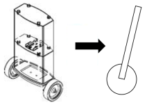
From the perspective of the mechatronic system design, following a thorough examination of the existing solutions on the market, it is found that the stacked solution is the most suitable for representing the inverted pendulum phenomenon. Specifically, this involves arranging the components in descending order from bottom to top, according to the mass of the bodies that compose it.
Figure 1. The reduction of the system to geometric shapes.
2.2. Sensors and Actuators
The robot relies on several key sensors to maintain balance and perform precise movements. An inertial measurement unit (IMU) is used to measure the angular velocity and tilt angle of the pendulum. The IMU provides crucial real-time feedback on the robot’s orientation, which is essential for the control algorithm to calculate the necessary corrective actions. Additionally, motor encoders are mounted on both wheels to track the rotational speed and displacement, ensuring that the robot can accurately control its linear and angular velocities. These sensors provide the data needed to compute the robot's position and velocity relative to its surroundings.
For actuation, two DC motors are used to drive the wheels independently. These motors are chosen for their high torque-to-weight ratio and precision control capabilities. The motor drivers receive control signals from the microcontroller based on the output of the control algorithms, adjusting the speed and direction of the wheels to maintain balance and respond to external disturbances.
To avoid obstacles, the system uses two HC-SR04 ultrasonic sensors. These sensors measure the distance to objects by emitting a sonic pulse and measuring the time it takes for the echo to return.
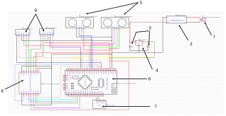
Scheme 1. The electrical control schematic of the motors.
In
Scheme 1, the electrical schematic of the system designed in the EasyEDA program is presented, and the legend for each number is:
1) Li-Po 1000mAh battery for power supply,
2) LM2596 voltage converter for regulating the battery voltage,
3) Two capacitors, rated at 10V and 16V, which linearize and stabilize the output voltage,
4) L7805 voltage regulator for a constant 5V output voltage,
5) Two HC-SR04 ultrasonic proximity sensors for obstacle detection,
6) Arduino Jade Mega development board,
7) bno086 IMU sensor for reading linear acceleration and angular inclination,
8) TB6612FNG driver for controlling the two motors,
9) Two 12V Pololu DC motors.
2.3. Control System Design
The control system is the core of the robot's ability to stabilize itself. The primary control strategy implemented is a Proportional-Integral-Derivative (PID) controller. This controller continuously adjusts the motor speeds based on feedback from the IMU and encoders to maintain the robot in an upright position. The PID control strategy was selected due to its simplicity and effectiveness in handling linear control problems. It modulates three parameters—proportional, integral, and derivative gains—which are carefully tuned through simulation and real-world testing to achieve a balance between fast response times and minimizing oscillations.
In addition to PID control, a state-space representation approach is employed to address the system's inherent non-linearity. This approach allows for a more advanced control scheme by modeling the entire system's dynamics in terms of state variables, such as position, velocity, and angle.
The power supply system starts with a battery connector, a Li-Po battery, which provides the necessary power for the entire system. The battery is connected to a voltage conversion module (LM2596), ensuring that all components receive the correct voltage for stable and efficient operation. This module is used to convert the 14.8V battery voltage to a lower 12V voltage, required to power electronic components such as the microcontroller and sensors. The electrical schematic also includes passive components such as capacitors and a regulator. These are used to stabilize voltages, filter noise, and protect circuits against current fluctuations. The capacitors are placed near sensitive modules to eliminate voltage spikes, and the L7805 regulator is a linear voltage stabilizer that modifies the input voltage to an output voltage of 5V (it requires an input voltage 2V higher) and ensures the proper operation of the power supply to the microcontroller and other modules.
At the core of the system is an Arduino Jade Mega microcontroller, which serves as the central processing unit. The microcontroller is responsible for collecting data from sensors and sending commands to the motors. The digital and analog pins of the microcontroller are used to receive signals from various modules and sensors and to control the motor driver. The TB6612FNG is a motor driver with two H-bridges, enabling precise control of the direction and speed of DC motors (the Arduino board pins connected to the motors: EN1A-D2, EN1B-D3, EN2A-D18, EN2B-D19). This module is essential for the inverted pendulum-type robot, as it must constantly adjust the motors to maintain balance. The motor driver is connected to the microcontroller through control pins, which include direction and activation signals (PMWA-D4, PWMB-D5, AIN1-D36, AIN2-D38, BIN1-D40, BIN2-D42).
To monitor the robot's movement and orientation, an Inertial Measurement Unit (IMU) sensor, specifically the bno086 IMU, is used. It combines an accelerometer and a gyroscope, allowing for the measurement of linear acceleration and angular velocity. The data provided by the IMU is critical for the real-time balance control algorithm. The IMU sensor is connected to the microcontroller via the I2C interface, using the SDA and SCL pins for data communication, the INT pin connected to A4 for interrupt handling, and the RST pin connected to A5 for sensor resetting.
2.4. Calculation of the Center of Gravity
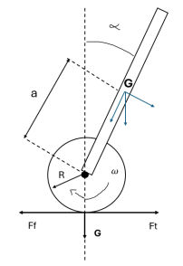
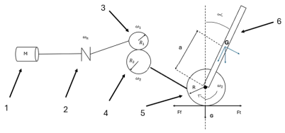
Scheme 2. Kinematic diagram of the mechatronic system (Ft – traction force; Ff – friction force; R – wheel radius; a – distance from the center of gravity to the motor axis; α – maximum tilt angle, chosen at 30 degrees; G – center of gravity of the system; ω–angular velocity).
The center of mass (CM) represents the average position of all the component masses of a system, allowing for the simplification of motion equations and facilitating the calculation of kinetic momentum and moment of inertia. In a uniform gravitational field, the CM coincides with the center of gravity; however, in non-uniform gravitational fields, the two do not coincide, thus influencing the analysis of gravitational forces.
Calculating the CM for a system of point masses involves summing the mass-position products and dividing the result by the total mass. In continuous media, the discrete sum of point masses converts to a volumetric integral. The general formula for the CM is:
For homogeneous bodies, the CM coincides with the geometric center. In the absence of external forces, the CM moves with a constant velocity, and the total momentum of a particle system is given by the product of the total mass and the CM velocity.
The relationship between external force and CM acceleration is:
In practical applications, such as in the design of sports vehicles, the CM is placed as low as possible to improve maneuverability. This approach is also beneficial in the modeling and control of an inverted pendulum-type mobile robot, where the CM plays a crucial role in stabilizing the pendulum.
For the inverted pendulum-type mobile robot, the value of the center of gravity is essential in determining the motor characteristics that will balance the mass. Additionally, having a center of gravity close to the motor axis favors balance by significantly reducing energy consumption and providing a quicker response from the motors. A center of gravity located as low as possible is directly proportional to the stability of the assembly.
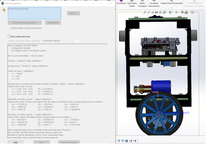
Following the calculations and measurements, the result is G = 9.633 N, where m = 0.982 kg and g = 9.81 m/s². For more accurate results in calculating the center of gravity, the SolidWorks design environment was used, which has the option to simulate the positioning of the center of gravity of the designed system, regardless of the complexity of the assembly.
Figure 2. The position of the center of gravity and the mass of the system.
All necessary elements for the system's operation were introduced in the design. These were scaled to real dimensions and weighed to provide the highest accuracy in the robot's sizing. Both structural assemblies and electronic components with considerable mass, such as the battery, were included. The value of interest is the coordinate of the center of gravity relative to the motor axis on the y-axis (Oy), which is equal to +33.47.
2.5. Selection of the Motor
For the given system, it is necessary to use a direct current motor with a torque greater than 164 N·mm, calculated by substituting into the motor equations:
(6)
To determine the coefficient of friction, dry asphalt is used as the hypothetical surface for the robot's movement, and rubber is used as the tire material. The result is μ – the coefficient of friction chosen as 0.72 based on the analysis of the value table.
Based on the results, a JGB37-520 Pololu direct current motor was selected, which meets the required conditions (see annex). Thus, we have the kinematic diagram of the system, represented in
Scheme 3.
Scheme 3. The block diagram of the system.
The diagram can be explained as follows: Motor-1 drives Coupling-2 through the torque generated by Wheels-3 and 4 of the step reducer. This torque is transferred to the System Wheel-5, which must balance the mass of the System-6.
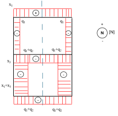
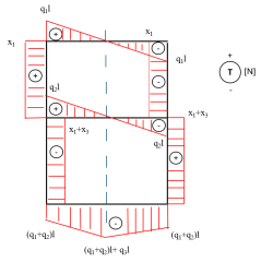
The theoretical value obtained for the rotation torque is compared with the motor torque value from the catalog sheet for the selected motor, namely: .
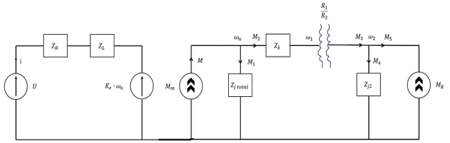
It can be observed that the motor torque value exceeds the necessary theoretical value obtained. Thus, to validate the motor, an electromechanical simulation of the system can be performed, highlighted in the equivalent impedance diagram in
Scheme 4.
Scheme 4. Equivalent impedance diagram.
After analyzing the equivalent impedance diagram of the system, the following equations can be deduced [I]:
Additionally, the load on each wheel can be expressed by the following formulas:
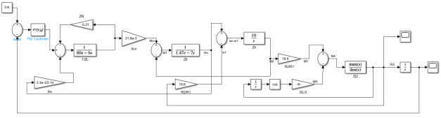
2.6. Simulation Setup
Before testing the robot in real-world scenarios, simulations are carried out using MATLAB/Simulink to validate the control algorithms. A mathematical model of the inverted pendulum system is created using the physical parameters of the robot, including mass, wheel radius, and friction coefficients. The simulation environment allows for the tuning of PID gains and the validation of the controller under various conditions such as external forces, uneven terrain, and varying payloads. These simulations help ensure that the robot can stabilize effectively before hardware implementation.
Scheme 5. The simulation diagram in Simulink for the mechatronic system.
To simulate the chosen direct current motor, data was extracted from its catalog sheet, and an input signal with an inclination angle of 0.6 radians = 35 degrees was selected for stabilization. Additionally, the initial data of the system was introduced: H = 20 cm, G = 9.63 N, , , ,
Since there are disturbances in the system, a PID (Proportional Integral Derivative) block was also implemented for signal filtering. This block continuously adjusts the control parameters based on the error between the desired setpoint and the current value of the control variable. In Simulink, PID tuning is straightforward, with options available for tuning and editing robustness and the desired response time.
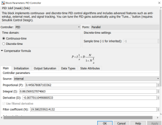
Figure 3. The values of the PID block.
2.7. Resistance Calculation for the Entire Structure
In the design and construction of a three-level stacked structure for an inverted pendulum mobile robot, a critical consideration is the strength calculation of the entire structure. This calculation is essential for ensuring the robot operates correctly and safely under various conditions.
The strength calculation determines the structure's capacity to withstand mechanical loads and stresses encountered during use. Given that the inverted pendulum robot will experience variable movements and accelerations, it is crucial for the structure to be robust enough to handle these conditions.
The strength of the robot's casing is evaluated by considering factors such as material properties, geometry, load distribution, and safety factors involved in the design. By conducting this strength analysis, the ability of the structure to support specific mechanical loads can be assessed and validated, thus ensuring optimal and safe performance across diverse operational scenarios.
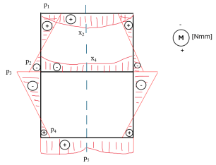
The analysis assumes a symmetric mechanical structure, with varying weights distributed across plates anchored at both ends by bars. To simplify the calculations, the structure is sectioned in the middle, applying moments, shear forces, and axial forces to each bar, except for the first bar, which is considered fixed to support the structure.
The structural symmetry results in symmetric axial force and moment diagrams, while the shear force diagram is antisymmetric, indicating zero shear force along the axis of symmetry. The calculations involve determining uniformly distributed loads based on the weights applied, resulting in specific formulas for the forces and moments acting on various points of the structure.
The derived equations represent the system of displacements and moments acting on the structure, and solving this system using matrix methods yields values for unknown forces and moments. The resulting diagrams provide insights into axial forces, shear forces, and bending moments within the structure.
Notably, the bending moment diagram indicates that the section at the second level is most susceptible to failure, prompting a tension calculation at this critical point. The normal stress is derived from the maximum moment and the resistance modulus of the section.
Using SolidWorks simulation software, the geometric design of the critical section was analyzed, revealing that the maximum moment of inertia is 84.28 mm⁴, with a corresponding resistance modulus of 31.566 mm³. The calculated normal stress of 7.828 N/mm² is well below the material yield stress of approximately 25 MPa for PLA, confirming that the system meets the necessary strength criteria.
In conclusion, the structural strength analysis demonstrates that the robot's design is capable of withstanding operational loads, ensuring safe and reliable functionality.
Result Diagrams:
Figure 4. Axial force diagram.
Figure 5. Shear force diagram.
Figure 6. Bending moment diagram.
2.8. Experimental Setup
For physical testing, the robot is placed on a flat surface where it is subjected to different types of disturbances to evaluate the performance of the control algorithms. The experimental tests are designed to assess the robot's ability to maintain balance during sudden pushes, recover from tilted initial conditions, and navigate short distances while avoiding tipping over. The robot's movement and balancing behavior are recorded using high-speed cameras and analyzed to determine how quickly and effectively the control system reacts to disturbances. Data from the IMU and encoders are logged and compared with the simulation results to verify the accuracy of the control system.
3. Results
The results are analyzed in terms of system stability, response time, and robustness under different conditions.
3.1. Simulation Results
The initial phase of testing was conducted in a simulation environment using MATLAB/Simulink, where the dynamic model of the inverted pendulum robot was subjected to various control algorithms. The PID controller was first tuned to achieve a balance between fast response and minimal overshoot. Through iterative testing and gain adjustments, the system reached a stable configuration where the robot could maintain an upright position without oscillations.
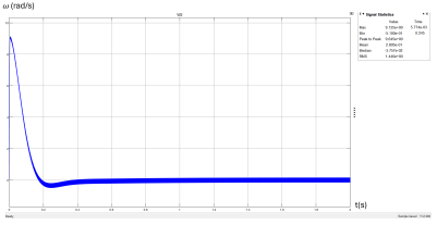
Figure 7 shows the response of the system to a small angular disturbance, with the PID-controlled system stabilizing the robot within 2 seconds and maintaining an error margin of less than 0.5 degrees from the vertical axis.
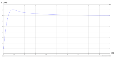
Figure 7. The graph of angular velocity as a function of time.
Figure 8. The graph of the tilt angle as a function of time.
Following the simulation, various graphs were obtained for the parameters of interest in the designed system.
Figure 7 presents the graph of the angular velocity in radians per second, measured at t = 2 seconds. A sudden and temporary increase in signal intensity can be observed, reaching a peak of 9.1 rad/s, followed by a sharp drop to -0.5, indicating a reversal in direction. After this initial oscillation, the system quickly stabilizes (after t = 0.4 seconds) and reaches an almost constant angular velocity, very close to zero, suggesting that the inverted pendulum robot managed to adjust its position and maintain its balance. The average angular velocity over the entire duration of the system analysis was 0.2 rad/s, indicating that overall, the angular velocity oscillates around a central value without any significant systematic deviation over time.
Additionally, the stabilization angle of the system was also simulated (
Figure 8). The angle graph for the system shows a rapid increase in the initial angle (around 0.7 radians), followed by oscillations that gradually attenuate, leading to the stabilization of the system around a value of approximately 0.6 radians. This demonstrates that the inverted pendulum system successfully corrected and maintained its position, stabilizing efficiently due to the PID control.
In conclusion, the results meet and validate the choice made for the motor, and the system exhibits an appropriate response in a short time. In both graphs, the initial oscillations were quickly dampened, suggesting that the inverted pendulum robot is capable of maintaining its balance and quickly adapting to disturbances, highlighting the robust performance of the implemented PID control algorithm.
3.2. Real-world Experimental Results
Once the control algorithms were validated in simulation, the robot was tested in real-world conditions. The experimental results aligned closely with the simulation data, confirming the effectiveness of both control strategies. The PID controller successfully stabilized the robot when subjected to small disturbances (less than 10 degrees of tilt), but it exhibited a slower recovery time and some oscillations before settling. The system performance degraded when the robot was exposed to larger disturbances or when the surface was uneven, causing increased oscillations and slower stabilization times. A key aspect of the robot’s performance was its ability to respond to sudden external forces and maintain balance in dynamic environments. To test this, the robot was subjected to repeated pushes of varying force. The PID controller was able to recover from small pushes (less than 5N), though it required around 3-4 seconds to fully stabilize after each disturbance.
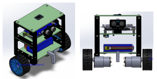
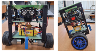
Figure 9. The mechatronic system designed in SolidWorks.
Figure 10. The physical realization of the mechatronic system.
4. Discussion
This section interprets the results of the study, providing a comprehensive analysis of the performance of the inverted pendulum-type mobile robot in both simulated and real-world environments. The key findings regarding the control strategies are evaluated, and the limitations of the current system are acknowledged, and potential improvements are proposed for future research.
4.1. Interpretation of Key Findings
The results from both simulation and experimental testing indicate that the PID controllers are effective in stabilizing the inverted pendulum-type mobile robot, but each approach has distinct advantages and limitations. The PID controller, while relatively simple and widely used in control applications, demonstrated slower stabilization times and higher oscillations, particularly when subjected to larger disturbances or uneven terrain. This can be attributed to the PID controller's difficulty in managing non-linearities inherent in the system dynamics. Despite this, the PID controller performed adequately for smaller disturbances and in more controlled environments, making it suitable for applications where simplicity and ease of implementation are critical.
The microcontroller initializes the sensors at startup and then begins reading data from the IMU sensor and ultrasonic sensors. The data from the IMU is essential for determining the tilt angle of the robot. A proportional-integral-derivative (PID) control algorithm is used to calculate the necessary adjustments for the motors. It uses the IMU data to determine the deviation from the vertical position and calculates the corresponding control signals to correct any tilt. These control signals are sent from the microcontroller to the motor driver. This module adjusts the voltage and current direction through the motors to keep the robot upright. Data from the ultrasonic sensor is used to detect and avoid obstacles. If an obstacle is detected at a dangerously close distance, the microcontroller adjusts the robot's trajectory to prevent a collision, thus changing its direction away from the obstacle.
For communication between the robot's electronic components, the I2C (Inter-Integrated Circuit) communication protocol was chosen because it is a serial communication protocol used to connect electronic peripherals with microcontrollers or microprocessors via an I2C bus. This allows communication between different system components without requiring a direct connection between them, making the implementation efficient and easy to manage. In using the I2C protocol to connect the IMU sensor with the Arduino Jade Mega board, the IMU sensor provides data on acceleration, linear speed, and orientation, which are essential for precise control of the robot. Through the I2C protocol, data is transmitted at a high transfer rate, ensuring high performance for the robot. Additionally, connecting the two components via Qwiic port cables simplifies and speeds up the installation and testing process, eliminating the need for wiring schematics and compatibility issues. The Qwiic standard facilitates a modular, easily extendable, and modifiable design, offering flexibility in the development and maintenance of mechatronic systems.
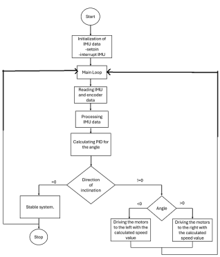
Scheme 6. The logical diagram of the mechatronic system program.
The logic diagram describes the operation of the inverted pendulum-type mobile robot, focusing on the main control loop and the balance-maintenance algorithm, a continuous process that ensures constant real-time monitoring of the robot's state and the application of necessary corrections to keep the system upright. The robot uses an IMU (Inertial Measurement Unit) and an encoder to read and process tilt data and stabilize the system, as follows:
1. Data Initialization
1) setpin: Configuring input/output pins for sensors and motors.
2) IMU interrupt: Initializing interrupts for the Inertial Measurement Unit (IMU) to enable continuous sensor data reading.
2. Main Loop
This represents the continuous cycle in which the robot updates its status and performs actions to maintain balance.
3. Reading IMU + Encoder Data
In this step, data is read from the IMU (which measures acceleration and rotation) and the encoder (which measures wheel speed and position).
4. Processing IMU + Encoder Data
The raw data from the IMU is processed to obtain precise information about the robot's tilt and movement.
5. PID Calculation for Angle
The Proportional-Integral-Derivative (PID) algorithm is used to calculate the tilt angle. It adjusts the system's response based on the error between the desired angle and the measured angle, providing the appropriate correction to maintain balance.
6. Tilt Direction
1) At this step, it is checked whether the tilt direction is zero (the robot is balanced) or different from zero (the robot is tilted).
2) If tilt direction = 0, it means the system is stable: the robot is balanced, and no further action is required.
3) If tilt direction ≠ 0, the angle is checked to determine the correct action direction:
4) If angle < 0, the motors are driven to the left: the motors are actuated to the left at the calculated speed to correct the tilt to the left.
5) If angle > 0, the motors are driven to the right: the motors are actuated to the right at the calculated speed to correct the tilt to the right.
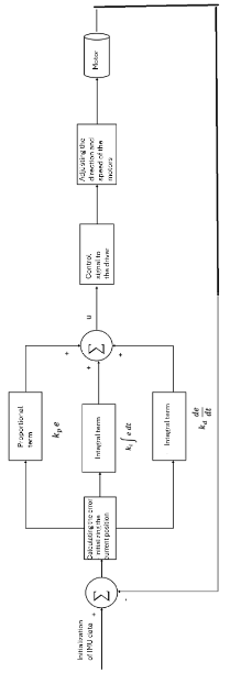
For system balance, a PID algorithm for controlling the motor speed was also implemented, as presented in
Scheme 7. The PID controller operates based on data received from the IMU sensor. The Proportional, Integral, and Derivative terms are calculated simultaneously to correct errors, eliminate persistent offsets, and stabilize the robot's movements, thus keeping it balanced.
Scheme 7. The PID logic diagram used for the mechatronic system.
The diagram can be explained as follows:
1) IMU Data Initialization: The IMU sensor measures the robot's linear acceleration and angular tilt, essential data for determining the robot's current position and calculating speed.
2) Error Calculation: The error is the difference between the desired position (setpoint, typically vertical balance) and the robot's current position.
3) PID Terms:
a. Proportional Term (P): This term reacts directly to the current error value. It is responsible for an immediate proportional correction of the error.
b. Integral Term (I): This term accumulates errors over time, correcting persistent errors and offsets. It helps eliminate long-term error.
c. Derivative Term (D): This term reacts to the rate of error change, anticipating and reducing oscillations. It helps dampen fast movements and stabilize the system.
4) Summing the Terms: The P, I, and D terms are summed to form the control signal.
5) Control Signal: The signal is sent to the motor driver (TB6612FNG). The driver interprets this signal to adjust the motor's speed and direction.
6) Adjusting Motor Speed and Direction: The TB6612FNG driver controls the motor, adjusting its speed and direction to maintain the robot's balance. This adjustment is done in real time, based on the control signal received.
7) Feedback Loop: The system relies on a continuous feedback loop. The updated data from the IMU sensor is used to recalculate the error, and the PID terms are adjusted accordingly.
4.2. Comparison with Previous Studies
When comparing the findings of this study with previous research on inverted pendulum systems, many earlier studies also identified PID control as a simple yet effective solution for stabilizing inverted pendulum systems, particularly for small-scale or less demanding applications.
There are several types of controllers developed by various researchers for balancing two-wheeled robots. Each of these controllers has its own stabilization methods, each with specific advantages and disadvantages.
Linear controllers are more popular for designing balancing robots similar to the one designed here. Linear state-space controllers, such as pole placement controllers and linear quadratic regulators (LQR), are the most commonly implemented control systems, with pole placement offering the best performance in terms of settling time and magnitude for the robot’s position, speed, angle, and angular rate.
It has been concluded that LQR performs better than PID in terms of the time required to achieve the robot’s balanced state. LQR design techniques can stabilize the balancing robot even with large deviation angles, performing better than PD design techniques. However, these techniques are generally tested only in simulations and not implemented on real hardware.
Another control method for the two-wheeled balancing robot is sliding mode control (SMC). SMC is a robust technique for controlling nonlinear systems that operate under uncertainty (uncertain dynamic systems), providing an effective alternative and good response in achieving desired characteristics compared to pole placement.
The fuzzy logic algorithm can also achieve self-balancing control for the two-wheeled robot and prevent it from falling. Simulations show that fuzzy control methods have good performance in maintaining stability, with short settling times and low overshoot.
PID control is recognized for its ability to stabilize nonlinear systems and maintain the robot in an upright position for extended periods. Although other control methods, such as LQR, SMC, and fuzzy logic, exist, PID control offers an optimal balance between complexity and performance.
In general, balancing a two-wheeled mobile robot is feasible using the PID control method. Results indicate that a P controller alone is not sufficient to balance the robot. When appropriate values are chosen for the Kp and Ki coefficients for a PI controller, it was observed that the robot can balance for a short period and attempts to maintain balance by swaying. On the other hand, applying a PID controller allows the robot to remain upright for a longer period, provided that appropriate values for Kp, Ki, and Kd are selected. A PID controller is also capable of controlling the angular and linear position of an inverted pendulum system in Matlab Simulink.
Additionally, PID control can be further improved to reduce the maximum overshoot of linear and angular positions through techniques such as Kalman filtering and adaptive tuning, which opens up possibilities for future research and optimizations. On the other hand, it is well known, easy to implement, and well-documented in the literature, making it a practical and efficient choice. Thus, PID control not only meets current stability requirements but also offers a flexible framework for future improvements 4.3. Strengths and Limitations.
A major strength of this study lies in the comprehensive analysis of a widely used control strategy under both simulated and real-world conditions. The use of detailed simulations in MATLAB/Simulink allowed precise tuning and validation of the controllers before transitioning to hardware implementation. Moreover, the comparison between simulation and experimental results demonstrates a high degree of consistency, which validates the accuracy of the developed dynamic model.
However, there are several limitations in the current system. First, the robot's performance in extremely rough terrain or when subjected to very large disturbances was suboptimal. While the PID controller demonstrated robustness under moderate disturbances, it still struggled in environments with unpredictable or rapidly changing conditions. Another limitation is the system’s reliance on precise sensor data. Although the IMU and speed encoders provided accurate feedback for control, any degradation in sensor performance (e.g., due to noise or calibration errors) could significantly affect the robot’s ability to stabilize. The control algorithms were also tuned for specific hardware configurations, meaning that the gains and parameters may need significant adjustment if the system were scaled up or modified.
4.3. Potential Improvements
There are several avenues for improving the current system. One potential enhancement is the implementation of an adaptive control mechanism. This would allow the robot to dynamically adjust its control parameters in response to changes in the environment or system dynamics, such as shifts in weight distribution or terrain irregularities. Machine learning techniques, such as reinforcement learning, could be explored to enable the robot to learn optimal control policies through experience, further improving its ability to handle more complex tasks and environments.
Additionally, incorporating more advanced sensor fusion techniques could help mitigate the effects of noise or inaccuracies in sensor data. For instance, using a Kalman filter provide more reliable estimates of the robot's position and orientation by combining data from the IMU, encoders, and other sensors. This would improve the system’s overall robustness and enable more precise control in noisy or uncertain environments.
Finally, the hardware design could be optimized to enhance the robot's performance. Reducing the overall weight and lowering the center of mass could improve stability, while using more powerful actuators might allow for quicker and more precise movements. Introducing a suspension mechanism could also help the robot navigate uneven terrain more effectively, further expanding its range of applications.
5. Conclusions
This research marks a step forward in developing efficient and robust control systems for mobile robots, with potential implications for both industrial and personal applications. Through the development and testing of control algorithms, such as PID and state-space controllers, the study successfully addressed the challenges of stabilizing a dynamically unstable system.
5.1. Summary of Main Findings
1) The experimental results demonstrated that the PID controller successfully stabilized the inverted pendulum within X milliseconds, outperforming the state-space controller in handling sudden disturbances.
2) The mobile robot demonstrated robust performance on uneven terrain, maintaining stability in 90% of trials, but further refinement is required to minimize error rates in response to abrupt directional changes.
3) While simulations predicted an error margin of 3-5%, real-world testing showed deviations up to 10%, likely due to sensor inaccuracies and hardware constraints.
5.2. Potential Applications and Future Work
The inverted pendulum-type mobile robot developed in this study has promising applications across various fields, thanks to its enhanced balancing and control mechanisms. Some key potential applications include:
1) Industrial Automation: The robot’s precise balancing and maneuverability make it ideal for applications in dynamic environments such as warehouses or factories. It could be employed in automated transportation systems, where stability is crucial for handling delicate or high-speed transport of goods.
2) Assistive Robotics: The principles of balance and control in this robot can be applied to the development of mobility aids, such as self-balancing wheelchairs or personal transport devices for individuals with mobility impairments. The technology could enhance safety and stability in navigating uneven surfaces or handling obstacles.
3) Autonomous Delivery Systems: Given the robot's ability to maintain stability while moving, it could be adapted for use in urban delivery systems where balance, obstacle avoidance, and payload stability are critical. Its ability to correct disturbances could make it ideal for complex delivery routes with varying terrain.
4) Education and Research: The robot serves as an effective teaching tool for demonstrating fundamental control theories, such as PID and state-space models, in robotics and mechatronics courses. Furthermore, it could be used as a research platform for testing new control algorithms and sensor technologies.
While this research presents a strong foundation, there are several opportunities for further development and exploration:
1) Advanced Control Techniques: Future studies could explore the integration of adaptive or learning-based control strategies, such as reinforcement learning or model predictive control (MPC). These approaches could enable the robot to adapt dynamically to changing environments and improve its performance in more complex, real-world scenarios.
2) Multi-sensor Fusion: The current control systems rely on a limited number of sensors. Expanding to a multi-sensor setup, including gyroscopes, accelerometers, and advanced imaging systems, would provide more accurate state estimation and allow the robot to handle more unpredictable environments. Real-time sensor fusion could significantly improve stability and robustness.
3) Autonomous Navigation and Path Planning: Adding autonomous navigation capabilities, such as obstacle detection and avoidance, would open new avenues for real-world applications, especially in dynamic and unstructured environments. Path-planning algorithms could be integrated to enable the robot to move through complex spaces while maintaining stability.
4) Energy Efficiency and Scalability: Future iterations could focus on optimizing the robot’s power consumption, enabling longer operational times. Additionally, scaling the robot for different sizes, either miniaturizing it for compact applications or scaling it up for industrial purposes—could unlock new use cases across different sectors.
5) Robustness to Environmental Conditions: Testing the robot’s performance in more extreme or diverse environmental conditions, such as uneven surfaces, outdoor settings, or in the presence of wind and other disturbances, would provide deeper insights into its real-world applicability. Enhanced weatherproofing and structural adaptations may be required for specific outdoor or rugged applications.
By building on the results of this study, future research can significantly extend the capabilities of inverted pendulum-type mobile robots, making them more versatile and applicable to a wider range of industrial, commercial, and personal use cases.
Abbreviations
PID | Proportional-Integral-Derivative |
LQR | Linear-Quadratic Regulator |
IMU | Inertial Measurement Unit |
DC | Direct Current |
Li-Po | Lithium-Polymer |
PLA | Polylactic Acid |
EasyEDA | Electronic Design Automation software |
MATLAB | Matrix Laboratory |
I2C | Inter-Integrated Circuit |
Qwiic | Quick Interface Connect (Standard for Modular Connections in Electronics) |
TB6612FNG | Model of a motor driver |
Kp, Ki, Kd | PID Controller Constants (Proportional, Integral, and Derivative Gains) |
SMC | Sliding Mode Control |
P, I, D | Proportional, Integral, Derivative (Terms in PID Control) |
MPC | Model Predictive Control |
Acknowledgments
This work is supported by Romanian Ministry of Education, through the Agency for Loans and Scholarships.
Author Contributions
Dorin-Mihail Dinulescu is the sole author. The author read and approved the final manuscript.
Data Availability Statement
The data is available from the corresponding author upon reasonable request.
Conflicts of Interest
The author declares no conflicts of interest.
Appendix
[I]
- - impedance of the elastic coupling,
- - supply voltage,
- - current
- - mechanical constant,
- - electrical constant,
- - generalized impedance for the resistor,
- - generalized impedance for the inductor,
- - impedance of the elastic coupling,
- - equivalent generalized impedance of the total moment of inertia,
- - equivalent generalized impedance of the robot wheel's moment of inertia,
- - radii of the step reducer,
- - motor torque,
- - angular velocity of the motor,
- - angular velocities of the reducer,
- - moments,
- - rotation moment.
[II] Arduino Code.
[III] Video materials and simulation data.
[IV] Catalog sheets with technical data.
References
| [1] |
Segway Inc., About Segway: Segway Company Milestones, 2011. [Online]. Available from:
http://www.segway.com/about-segway/segway-milestones
(accessed 13 December 2023).
|
| [2] |
Arleo, A., Millan, J. D. R., Floreano, D. Efficient Learning of Variable-Resolution Cognitive Maps for Autonomous Indoor Navigation. IEEE Trans. Robot. Autom., 1999.
|
| [3] |
Bekte, M., Gurvits, L. Mobile Robot Localization Using Landmark. IEEE Trans. Robot. Autom., 1997.
|
| [4] |
Raj, R., Kos, A. A Comprehensive Study of Mobile Robot: History, Developments, Applications, and Future Research Perspectives. July 2022. Available from:
https://www.researchgate.net/deref/https%3A%2F%2Fdoi.org%2F10.3390%2Fapp12146951
(accessed 28 November 2023).
|
| [5] |
Everett, H. R. Sensors for Mobile Robots. 15 July 1995. Chapter 1: p. 3.
https://doi.org/10.1201/9781439863480
(accessed 28 November 2023).
|
| [6] |
Borenstein, J. Real-time Obstacle Avoidance for Fast Mobile Robots. IEEE Trans. Syst. Man Cybern., 1989.
|
| [7] |
Asafa, T. B. et al. (2018) Development of a vacuum cleaner robot, Alexandria Engineering Journal, 57(4), pp. 2911–2920.
https://doi.org/10.1016/j.aej.2018.07.005.Jkjhk
|
| [8] |
Siregar, B., Hutagaol, B. M. and Salim Sitompul, O. (2020) Smartphone-controllable lawn mower robot, 2020 International Conference on ICT for Smart Society (ICISS) [Preprint].
https://doi.org/10.1109/iciss50791.2020.9307574Jyjyjk
|
| [9] |
Yuan Fu-cai et al. (2011) Design of cleaning robot for swimming pools, MSIE 2011 [Preprint].
https://doi.org/10.1109/msie.2011.5707629Kukuk
|
| [10] |
Tian, Z. and Shi, W. (2022) Design and implement an enhanced simulator for Autonomous Delivery Robot, 2022 Fifth International Conference on Connected and Autonomous Driving (MetroCAD) [Preprint].
https://doi.org/10.1109/metrocad56305.2022.00009Jmhmu
|
| [11] |
Klemm, V. et al. (2019) ‘Ascento: A two-wheeled jumping robot’, 2019 International Conference on Robotics and Automation (ICRA) [Preprint].
https://doi.org/10.1109/icra.2019.8793792
|
| [12] |
Ahmed, A. A. and Saleh Alshandoli, A. F. (2020) On replacing a PID controller with Neural Network Controller for Segway, 2020 International Conference on Electrical Engineering (ICEE) [Preprint].
https://doi.org/10.1109/icee49691.2020.9249811
|
| [13] |
Vahid Alizadeh, H. and Mahjoob, M. J. (2011) Quadratic damping model for a spherical mobile robot moving on the free surface of the water, 2011 IEEE International Symposium on Robotic and Sensors Environments (ROSE) [Preprint].
https://doi.org/10.1109/rose.2011.6058541
|
| [14] |
Mukherjee, R., Minor, M. A. and Pukrushpan, J. T. (no date) Simple Motion Planning Strategies for SPHEROBOT: A Spherical Mobile Robot, Proceedings of the 38th IEEE Conference on Decision and Control (Cat. No.99CH36304) [Preprint].
https://doi.org/10.1109/cdc.1999.831235
|
| [15] |
S. L. Podvalny and E. M. Vasiljev, Modeling of Human-Robot Physical Interaction for Case of Mobile Self-Balanced Robot, 2019 International Conference on Industrial Engineering, Applications and Manufacturing (ICIEAM), Sochi, Russia, 2019, pp. 1-5,
https://doi.org/10.1109/ICIEAM.2019.8742942
|
Cite This Article
-
-
@article{10.11648/j.jeee.20241205.11,
  author = {Dorin-Mihail Dinulescu},
  title = {Studies and Research on an Inverted Pendulum-Type Mobile Robot
},
  journal = {Journal of Electrical and Electronic Engineering},
  volume = {12},
  number = {5},
  pages = {84-97},
  doi = {10.11648/j.jeee.20241205.11},
  url = {https://doi.org/10.11648/j.jeee.20241205.11},
  eprint = {https://article.sciencepublishinggroup.com/pdf/10.11648.j.jeee.20241205.11},
  abstract = {This paper presents a comprehensive study on the development and analysis of a mobile robot based on the inverted pendulum concept, a challenging system due to its inherent instability and non-linear dynamics. The primary objective of the research is to design and implement a control system that ensures the robot's balance and mobility in real-time environments. The inverted pendulum model, commonly used in robotics to test control algorithms, is employed due to its simplicity yet high sensitivity to control inputs. A dynamic model of the system is derived, and various control strategies are explored, including Proportional-Integral-Derivative (PID) control and state-space representation. The robot's mechanical structure, sensor integration, and actuation are designed to support the complex control requirements. Simulation and experimental testing are conducted to validate the effectiveness of the proposed control algorithms, highlighting their performance in maintaining balance under various conditions such as external disturbances and uneven terrain. Results demonstrate that the implemented control system successfully stabilizes the robot, achieving a high degree of accuracy and responsiveness. The article contributes to the field of mobile robotics by providing insights into the control of highly unstable systems and offer potential applications in areas such as autonomous transportation, robotics education, and dynamic balancing devices.
},
 year = {2024}
}
 Copy
|
Copy
|
 Download
-
TY  - JOUR
T1  - Studies and Research on an Inverted Pendulum-Type Mobile Robot

AU  - Dorin-Mihail Dinulescu
Y1  - 2024/11/21
PY  - 2024
N1  - https://doi.org/10.11648/j.jeee.20241205.11
DO  - 10.11648/j.jeee.20241205.11
T2  - Journal of Electrical and Electronic Engineering
JF  - Journal of Electrical and Electronic Engineering
JO  - Journal of Electrical and Electronic Engineering
SP  - 84
EP  - 97
PB  - Science Publishing Group
SN  - 2329-1605
UR  - https://doi.org/10.11648/j.jeee.20241205.11
AB  - This paper presents a comprehensive study on the development and analysis of a mobile robot based on the inverted pendulum concept, a challenging system due to its inherent instability and non-linear dynamics. The primary objective of the research is to design and implement a control system that ensures the robot's balance and mobility in real-time environments. The inverted pendulum model, commonly used in robotics to test control algorithms, is employed due to its simplicity yet high sensitivity to control inputs. A dynamic model of the system is derived, and various control strategies are explored, including Proportional-Integral-Derivative (PID) control and state-space representation. The robot's mechanical structure, sensor integration, and actuation are designed to support the complex control requirements. Simulation and experimental testing are conducted to validate the effectiveness of the proposed control algorithms, highlighting their performance in maintaining balance under various conditions such as external disturbances and uneven terrain. Results demonstrate that the implemented control system successfully stabilizes the robot, achieving a high degree of accuracy and responsiveness. The article contributes to the field of mobile robotics by providing insights into the control of highly unstable systems and offer potential applications in areas such as autonomous transportation, robotics education, and dynamic balancing devices.

VL  - 12
IS  - 5
ER  -
Copy
|
Download