Abstract
To verify the reliability of the composite anchoring system consisting of chemical anchors and anchoring adhesive for the external prestressing reinforcement of concrete T-beams, this study conducted a systematic investigation through laboratory tests, theoretical derivations, and finite element simulations using MIDAS/FEANX. Tensile pull-out tests were designed using chemical anchors with three diameters (12, 16, and 20 mm) and five embedment depths ranging from 5D to 10D. Concurrently, tests were conducted on C50 concrete specimens to evaluate the bond strength at the adhesive interface and the composite anchorage capacity. Relevant theoretical formulas were derived, numerical models were established, and the failure modes and load differences were compared and analyzed. The results indicate that chemical anchors primarily exhibit a combined conical-adhesive failure mode. For 16 mm anchors with embedment depths ranging from 6.5D to 10D, the safety factor reaches 1.45 to 2.02. The anchoring adhesive increases the initial stiffness of the steel anchor seat by 42.6%, and the ultimate load-bearing capacity of the composite system is 93.7% higher than that of specimens using pure anchoring adhesive. The average error between the theoretically derived formula and experimental values was 5.8%, and the relative error between finite element simulation results and experimental values was 5.3%, both demonstrating high accuracy.
Keywords
Post-tensioning Reinforcement, Steel Anchorages, Anchorage Bearing Capacity Testing, Finite Element Analysis
1. Introduction
As concrete T-beams age, traffic loads increase, and environmental erosion takes its toll, their load-bearing capacity deteriorates. External prestressed carbon fiber plate reinforcement technology has become the mainstream repair solution due to its significant effectiveness and ease of construction
. As the core load-transferring component of this technology, the anchoring reliability of steel anchor sockets directly determines the quality of the reinforcement project.
| [3] | Cook, R. A., Doerr, G. T., Klingner, R. E. Bond stress model for design of adhesive anchors. ACI Structural Journal. 1993, 90(5), 514–524. https://doi.org/10.14359/51626427 |
| [4] | Cook, R. A., Kunz, J., Fuchs, W., Konz, R. C. Behavior and design of single adhesive anchors under tensile load in uncracked concrete. ACI Structural Journal. 1998, 95(1), 9–25. https://doi.org/10.14359/522 |
| [5] | Cook, R. A. Behavior of chemically bonded anchor. Journal of Structural Engineering. 1993, 119(9), 2744–2762.
https://doi.org/10.1061/(ASCE)0733-9445(1993)119:9(2744) |
[3-5]
However, in practical engineering applications, steel anchor sockets may face various failure modes, such as cracking at the anchor bolt location, anchor bolt pull-out, anchor bolt shearing, or lifting of the steel anchor socket.
| [6] | Burton C, Visintin P, Griffith M C. Laboratory investigation of pull-out capacity of chemical anchors in individual new and vintage masonry units under quasi-static, cyclic and impact load [J]. Structures, 2021, 34: 901-930.
https://doi.org/10.1016/j.istruc.2021.08.016. |
[6]
Furthermore, the thin web structure of concrete T-beams limits the anchorage depth of the anchor bolts, and drilling often damages the reinforcing bars, making traditional post-anchoring techniques difficult to meet engineering requirements
| [7] | Wu, G., Wu, Z. S., Wei, Y., et al. Theoretical Analysis of Prestressed High-Strength Steel Wire Rope for Flexural Reinforcement of Reinforced Concrete Beams. Journal of Civil Engineering. 2007, 40(12), 28–37.
https://doi.org/10.15951/j.tmgcxb.2007.12.005 |
| [8] | Yu X R, Khodadadi N. Computational intelligence model for predicting the compressive strength of FRP-confined concrete column [J]. Structural Concrete,2025,26(3):1721-1738.
https://doi.org/10.1002/suco.70374 |
[7, 8]
.
Scholars both domestically and internationally have conducted extensive research on post-tensioning techniques; however, existing studies primarily focus on the tensile and shear performance of single anchor bolts
| [9] | Meva, M., Cook, R. A., Krishnamurthy, K. Pullout simulation of post installed chemically bonded anchors. Journal of Structural Engineering. 1996, 122(9), 1016–1024.
https://doi.org/10.1061/(ASCE)0733-9445(1996)122:9(1016) |
| [10] | Zhang, H. W., Smith, S. T. FRP-to-concrete joint assemblages anchored with multiple FRP anchors. Composite Structures. 2012, 94, 403–414.
https://doi.org/10.1016/j.compstruct.2011.07.025 |
[9, 10]
. There is a lack of systematic research—spanning experimental verification, theoretical analysis, and numerical comparison—regarding the load-bearing capacity of steel anchor plates in chemical anchor-adhesive composite anchoring systems under confined anchoring surfaces. Consequently, engineering design often relies on empirical formulas, resulting in insufficient accuracy. Therefore, against the backdrop of actual bridge retrofitting projects, this study conducts laboratory tests on composite anchoring systems, derives theoretical load-bearing capacity formulas for anchor bolts, anchoring adhesives, and the composite system, and combines finite element modeling with parametric simulation to reveal the failure mechanisms and stress characteristics of the composite anchoring system. The study proposes optimal engineering design parameters to provide comprehensive technical support for similar bridge retrofitting projects.
2. Test Plans and Performance Testing
To investigate the mechanical properties and load-bearing mechanisms of the chemical anchor-adhesive composite anchoring system, experimental research was conducted following a logical sequence focusing on material characteristics, core components, and the system as a whole. Basic material tests were performed to determine key parameters such as the shear strength of the chemical anchor and the mechanical properties of the concrete substrate; Pull-out tests were conducted on the chemical anchors to analyze the effects of diameter and embedment depth on their load-bearing capacity; tests on the interfacial bonding properties of the anchoring adhesive were performed to verify the interfacial bond strength and failure characteristics; finally, load-bearing capacity tests were conducted on the steel anchor seat composite anchoring system to reveal the system’s load-sharing mechanisms and ultimate load-bearing capacity, thereby providing experimental support for subsequent theoretical derivations and engineering applications.
2.1. Test Materials and Performance Testing
2.1.1. Chemical Anchor
High-strength chemical anchors from the same production batch were used to conduct double-shear tests on 16-mm anchors (five specimens per group). The average shear strength measured was 596.6 MPa. The test results showed low variability, and the yield strength was consistent; the material properties met the requirements of the specifications
| [11] | Qi Xiaoming, Lei Xu, Liu Xiaoyan, et al. Theoretical Analysis and Pull-out Test of Chemical Anchors for Concrete Substrate Bearing Capacity [J]. Journal of Changsha University of Science and Technology (Natural Science Edition), 2024, 21(2): 72-80. https://doi.org/10.19951/j.cnki.1672-9331.20220920002 |
[11]
.
Table 1. Test Results on the Mechanical Properties of Anchor Bolts.
Anchor bolt diameter (mm) | Shear Force/kN | Shear Strength/MPa |
16 | 73.9 | 602.2 |
16 | 76.8 | 626.2 |
16 | 71.2 | 580.5 |
16 | 68.9 | 559.7 |
16 | 75.4 | 614.6 |
2.1.2. Concrete Substrate
C50 concrete was prepared as the bearing foundation structure of anchor bolt, and the performance test was completed. The average compressive strength of concrete was 47.5 MPa, and the average elastic modulus was 3.43×10⁴MPa, which met the test requirements.
Table 2. Measured concrete parameter values.
Specimen No | Compressive Strength/MPa | Modulus of Elasticity/×10⁴ MPa |
1# | 47.2 | 3.43 |
2# | 49.3 | 3.47 |
3# | 46.1 | 3.40 |
2.1.3. Anchoring Adhesive
The two-component planting glue is used to test the bonding strength of 12.6 MPa, which is suitable for the interface bonding between steel anchor seat and concrete substrate and anchor bolt planting.
2.2. Tensile Pull-Out Strength Test for Chemical Anchors
2.2.1. Experimental Design
The control variable method was used to carry out the test. The variables were anchor bolt diameter (12, 16, 20mm) and 5D, 6.5D, 8D, 9D, 10D five embedding depth, each group of three parallel specimens. The static single pull-out test was carried out by anchor bolt pull-out tester. The ultimate bearing capacity, failure mode and load-displacement curve of the specimens were recorded, and the cracking of concrete and the bonding state of anchorage adhesive were observed.
2.2.2. Test Results
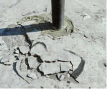
All test specimens exhibited a cone-bond failure mode (
Figure 1). No cases of pure steel rupture or pure pull-out failure were observed; only when the 20-mm anchor was embedded to a depth of 10D did slight signs of steel yielding appear. This indicates that, when the embedment depth is sufficient, the bearing capacity of the anchor is primarily governed by the concrete strength.
Figure 1. Diagram of anchor bolt pull-out failure.
The test results show that the pull-out bearing capacity of anchor bolts with different diameters increases nonlinearly with the increase of buried depth. When the buried depth increases from 5D to 8D, the bearing capacity is significantly improved; after exceeding 8D, the increase slowed down (
Tables 1-3). Among them, the peak load of 12 mm anchor bolt is 41.5kN when the buried depth is 8D, which is 81.2% higher than that of 5D; when the buried depth of 16 mm anchor bolt is 10 D, the peak load is 63.5kN, which is 64.1% higher than that of 5D. The peak load is 81.9kN when the buried depth of 20mm anchor bolt is 10D, which is 33.4% higher than that of 5D. Considering the difficulty and economy of site construction, it is suggested that the buried depth of 12 mm anchor bolt should be 6.5D ~ 8D, and the buried depth of 16 mm and 20 mm anchor bolt should be 6.5D ~ 10D
| [12] | Giresini L, Puppio M L, Taddei F. Experimental pull-out tests and design indications for strength anchors installed in masonry/concrete under small spacing constraint [J]. Materials and Structures, 2023, 56(7): 129.
https://doi.org/10.1617/s11527-023-02197-9 |
[12]
.
Table 3. Summary of Tensile Test Results.
Anchor bolt diameter (mm) | Design burial depth | Average bond strength / MPa | Measured tensile load capacity / kN | Maximum displacement (mm) |
12 | 5D | 11.61 | 22.9 | 0.29 |
12 | 6.5D | 8.62 | 23.8 | 0.58 |
12 | 8D | 11.63 | 41.5 | 0.62 |
12 | 9D | 7.00 | 27.7 | 0.55 |
12 | 10D | 8.95 | 36.7 | 0.36 |
16 | 5D | 9.75 | 38.7 | 0.30 |
16 | 6.5D | 8.86 | 45.5 | 0.31 |
16 | 8D | 8.49 | 54.1 | 0.26 |
16 | 9D | 7.46 | 54 | 0.33 |
16 | 10D | 8.73 | 63.5 | 0.43 |
20 | 5D | 10.91 | 61.4 | 0.32 |
20 | 6.5D | 7.53 | 54.5 | 0.40 |
20 | 8D | 8.13 | 75.1 | 0.47 |
20 | 9D | 6.84 | 76.1 | 0.31 |
20 | 10D | 6.56 | 81.9 | 0.35 |
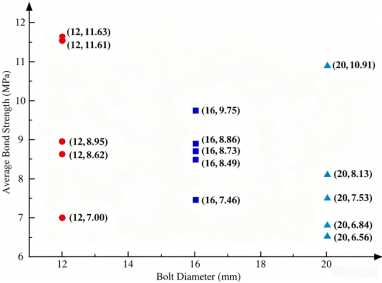
Analysis of the load-displacement data obtained from the tests reveals that, for the same diameter, the ultimate bearing capacity increases with greater embedment depth; for the same embedment depth, the ultimate bearing capacity increases linearly with diameter, primarily due to the increased cross-sectional area of the anchor bolt, which enhances both the bond strength and the bolt’s inherent tensile capacity. At the same time, the average bond strength shows a decreasing trend with increasing diameter. The average bond strengths for 12, 16, and 20 mm anchor bolts are 7.00–11.63 MPa, 7.46–9.75 MPa, and 6.56–10.91 MPa, respectively, indicating that larger-diameter anchor bolts have lower bonding efficiency.
Figure 2. Distribution of Average Bond Strength by Anchor Diameter.
2.3. Testing of the Interfacial Adhesion Properties of Anchor Adhesives
2.3.1. Experimental Design
In this experiment, four anchorage adhesive bonding specimens were made, numbered YJ-1 ~ YJ-4. The steel anchor seat is made of Q345 steel with a size of 450mm×250mm×20mm. The specimens were made according to the on-site construction technology, and the steel anchor seat was installed after the bonding surface was evenly painted with anchoring adhesive. The test is loaded by jack. If the steel anchor seat falls off or the load drops sharply, the failure of the specimen is determined and the loading is stopped.
2.3.2. Test Results
From the experimental phenomena, the failure load results of each specimen are summarized in
Tables 1-4. The failure load difference of the four specimens is obvious. The failure load of the 2 # specimen is 201 kN, and that of the 3 # specimen is only 114 kN. The difference between the two is large, and the average failure load of the specimen is 159.5 kN. This difference is mainly due to the different uniformity of anchorage adhesive brushing.
Table 4. Summary of Test Results.
Specimen | Specimen No. | Failure Load/kN | Average Failure Load/kN | Average Bond Shear Strength/MPa |
1#test piece | YJ-1 | 188 | 159.5 | 29.9 |
2#test piece | YJ-2 | 201 | 31.8 |
3#test piece | YJ-3 | 114 | 17.9 |
4#test piece | YJ-4 | 135 | 21.1 |
Although the load-displacement curves of the specimens were consistent, their mechanical properties differed significantly: the average bond shear strength was 29.9 MPa, 31.8 MPa, 17.9 MPa, and 21.1 MPa, respectively. The failure load of the YJ-2 specimen (201 kN) was 1.8 times that of the YJ-3 specimen (114 kN). This discrepancy may be related to the thoroughness of mixing the anchoring adhesive, the interfacial contact area, and the adhesive layer thickness. Additionally, the YJ-3 specimen’s curve exhibits an inflection point at 100 kN, indicating uneven stress distribution, whereas the remaining specimens experienced relatively uniform stress distribution.
2.4. Load-bearing Capacity Test of Steel Anchor Base Composite Anchors
2.4.1. Experimental Design
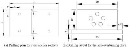
Design four sets of composite anchorage specimens using 16-mm-diameter chemical anchors (four per set) embedded to a depth of 10D. The base material and steel anchor sockets shall conform to the specifications used in the actual project. Apply loads in stages using a jack until the specimens fail, recording the ultimate load, failure mode, force distribution within the anchors, and concrete cracking characteristics.
Figure 3. Dimensions of Steel Anchor Sockets and Drilling Locations.
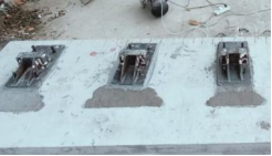
Figure 4. Test specimen for anchor base load-bearing capacity testing.
2.4.2. Test Results
Excluding Test Specimen No.1, which exhibited anchor bolt slippage, the remaining three groups of composite anchorage specimens had an average failure load of 309.0 kN, representing a 93.7% increase compared to the specimens using pure anchoring adhesive. The failure mode for all specimens was cracking of the anchoring adhesive combined with shear failure of the anchor bolts (
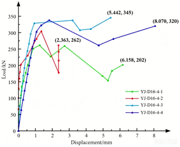
Figure 8). In Specimen No.2, three anchor bolts sheared (failure load: 262 kN); in Specimen No.3, two anchor bolts sheared (failure load: 345 kN); Specimen No.4 had 4 anchor bolts sheared (failure load 320 kN). This was primarily due to uneven stress distribution among the anchor bolts, with the front row bearing greater shear forces; the redistribution of stress following adhesive failure further exacerbated these stress disparities. The failure load of the steel anchor seat is not directly related to the number of failed anchor bolts; its load-bearing capacity is closely related to the installation position of the anchor bolts and the load distribution.
Table 5. Test Failure Results.
Specimen | Specimen No. | Failure Load/kN | Average Failure Load/kN | Number of failed bolts |
1# | YJ-D16-4-1 | 202 | 309.0(2#-4#) | 0 pieces |
2# | YJ-D16-4-2 | 262 | 3 pieces |
3# | YJ-D16-4-3 | 345 | 2 pieces |
4# | YJ-D16-4-3 | 320 | 4 pieces |
Figure 5. Load-displacement curve.
3. Theoretical Derivation and Verification of Anchor Bearing Capacity
3.1. Calculation of the Tensile Uplift Resistance of Chemical Anchors
The failure of chemical anchors is primarily due to a combination of cone and adhesive failure (based on test results). Their load-bearing capacity is determined by both the failure load of the concrete cone and the adhesive bond strength of the anchor; therefore, theoretical derivations must take both mechanisms into account.
The standard value of the failure load of the concrete cone is calculated using Equation (
1)
| [13] | Cook, R. A., Doerr, G. T., Klingner, R. E. Bond stress model for design of adhesive anchors. ACI Structural Journal. 1993, 90(5), 514–524. https://doi.org/10.14359/51626427 |
[13]
:
(1)
In the equation:
: Margin influence coefficient, ;
: Load eccentricity factor; when there is no eccentricity, take 1.0.
Calculation of Mixed Failure Tensile Strength (Bond Control) For standard chemical anchors, the standard value of the tensile strength at mixed failure is calculated using Equation (
2) below:
(2)
In the equation:
: Standard value of the adhesive bond strength of the anchor adhesive (MPa);
Since the failure of the anchor bolts in the test was a combined conical-adhesive failure, the interaction between the two failure modes must be taken into account. The ultimate bearing capacity is calculated using the superposition formula:
(3)
The theoretical values of the tensile pull-out resistance for anchor bolts of different diameters and embedment depths were calculated using Equation (
3) above and compared with the experimental measured values; the results are shown in
Table 6. As shown in the table, the relative error between the theoretical calculated values and the experimental measured values ranges from 3.8% to 8.5%, with an average error of 6.2%, which is less than 10%. This indicates that the derived composite failure load-bearing capacity formula can accurately predict the pull-out resistance of chemical anchors. The error is primarily attributed to the actual bond strength of the anchoring adhesive being slightly lower than the factory-specified value.
Table 6. Comparison of Theoretical and Experimental Tensile Uplift Strength Values for Chemical Anchors.
Anchor Bolt Diameter/mm | Embedment Depth | NRk/kN (Theoretical Value) | Test Value/kN | Relative Error |
12 | 8D | 12.9 | 13.5 | 4.4% |
16 | 10D | 27.2 | 29.1 | 6.5% |
20 | 10D | 38.9 | 41.6 | 6.5% |
16 | 6.5D | 17.8 | 19.4 | 8.2% |
20 | 8D | 26.8 | 28.0 | 4.3% |
3.2. Calculation of Interface Bond Strength for Anchoring Adhesives
The bond strength between the anchoring adhesive and the concrete interface is influenced by the concrete strength, the properties of the adhesive, and the surface roughness. Based on shear strength theory, the formula for the ultimate bond strength at the interface is:
In the equation:
Coefficient of influence for concrete properties, determined by experimental fitting to be 0.32;
Coefficient of influence for anchor adhesive properties, determined by experimental fitting to be 0.75;
The ultimate bond strength at the anchoring adhesive interface was calculated using Equation (
4) and compared with experimental measurements (
Table 7). The results show that the relative error between the theoretical values and the experimental measurements ranged from 2.9% to 7.8%, with an average error of 5.3%. The formula accurately reflects the bonding performance at the anchoring adhesive interface, and both concrete surface treatment and the quality of adhesive application significantly affect the bond strength.
Table 7. Comparison of Theoretical and Experimental Interface Bond Strength Values for Anchoring Adhesive.
Specimen Number | Measured Test Value/MPa | Relative Error |
YJ-1 | 29.9 | 4.0% |
YJ-2 | 31.8 | 7.8% |
YJ-3 | 27.9 | 2.9% |
YJ-4 | 29.5 | 2.8% |
3.3. Calculation of the Ultimate Load-Carrying Capacity of Composite Anchorage Systems
When determining the ultimate load-bearing capacity of a composite anchoring system (chemical anchor + anchoring adhesive), the synergistic effect between the shear capacity of the anchor and the bond strength of the anchoring adhesive must be taken into account. The calculation formula is derived based on the principle of force equilibrium.
Shear capacity of a group of anchors: The standard value of the shear capacity of a single anchor is calculated using the formula specified in the code:
The total shear capacity of the anchor group must account for the stress non-uniformity factor (calculated from the experimental stress distribution, as the front row of anchor bolts is subjected to greater stress):
(6)
Formula for the ultimate load-bearing capacity of a composite system:
(7)
In the equation:
: represents the residual bond strength of the anchor adhesive, taken as 30%–40% of the ultimate value (10.2 MPa in this paper);
Using Equation (
7) to calculate the ultimate load-bearing capacity of the composite anchoring system consisting of four 16-mm anchor bolts, the theoretical value is 298.6 kN, the experimental average is 309.0 kN, and the relative error is 3.4%; the finite element simulation value is 292.5 kN, with a relative error of 2.1%. The three values are in close agreement, verifying the accuracy of the theoretical derivation.
4. Finite Element Model Development and Validation
4.1. Material Constitutive Relations and Parameter Assignment
A three-dimensional finite element model was established using MIDAS/FEANX. The concrete was modeled using the C50 elastic model, while the steel anchor seat and anchor bolts were modeled using the Q345 steel elastic model; the material parameters were consistent with those from the experiments.
Since the ultimate load-bearing capacity of the anchoring system is primarily controlled by the mechanical properties of the anchor bolts, slippage at the adhesive interface was neglected, and the focus was placed on the shear stress state of the anchor bolts. A forced displacement was applied to the steel anchor seat along the shear direction (consistent with the test), and the load-displacement curve and stress distribution contour plots were extracted.
Figure 6. Application of concentrated force.
4.2. Model Validation Results
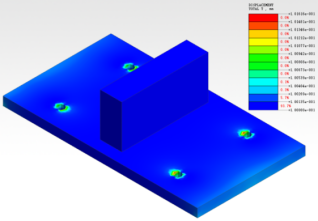
The results of the static analysis show that the overall displacement of the steel anchor seat in
Figure 10 is approximately 0.1 mm. Due to the anchoring bolts and the imposed displacement (0.03 mm), relative displacement occurs at the anchor seat hole, with a maximum displacement of 0.117 mm. The maximum normal stress in the direction of the shear force at the hole is 72.5 MPa, and the maximum shear strain in the XY plane is 1.17×10⁻³ mm. Neither value exceeds the ultimate load-bearing capacity of the steel anchor seat.
Figure 7. Contour plot of total displacement of the steel anchor seat.
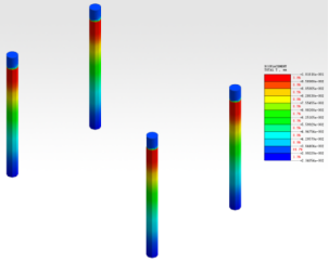
The displacement contour plot of the anchor bolt is shown in
Figure 11. The displacement at the interface between the anchor bolt and the concrete is small; the displacement at the interface with the steel anchor seat is approximately 0.1 mm; and a displacement of 0.033 mm occurs in the Z direction due to the pull-out force. The maximum shear stress is 1.5 × 10³ MPa. The force exerted by the steel anchor seat on the anchor bolt is 79.8 kN, which is essentially consistent with the load corresponding to the test displacement and significantly less than the average failure load of the test.
Figure 8. Contour plot of the anchor bolt's displacement in the X direction.
Figure 9. ZX-plane stress contour plot for concrete.
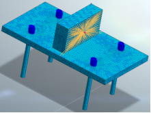
Figure 9 shows the stress distribution inside the concrete. The displacement at the interface between the concrete base and the steel anchor is 0.1 mm, and the maximum shear force in the ZX plane is 21.6 MPa. The concrete around the anchor bolt is fan-shaped stress distribution, which is prone to stress concentration damage. The maximum stress in the Z direction reaches 10.1 MPa, which is mainly caused by the transfer of the pullout force of the anchor bolt.
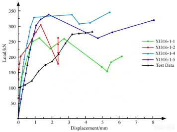
Figure 10. Comparison of load-displacement curves from finite element simulation and experimental results.
5. Parametric Simulation and Optimization Design
Based on the basic parameters of four 16-mm anchor bolts, four sets of simulation models with different parameters were designed to investigate the effects of the number and diameter of anchor bolts on anchoring performance.
Table 8. Summary of Specimen Information.
Anchor bolt diameter (Ф/mm) | Number of anchor bolts | With/without anchor adhesive | Specimen number |
16 | 6 | find | YJ-D16-6-1 |
16 | 8 | find | YJ-D16-8-1 |
18 | 4 | find | YJ-D18-4-1 |
20 | 4 | find | YJ-D20-4-1 |
5.1. Analysis of the Effect of the Number of Anchor Bolts on Anchoring Performance
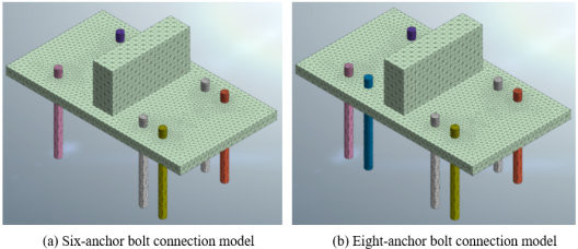
The simulation models for the YJ-D16-6-1 and YJ-D16-8-1 test specimens are based on the modeling parameters for the concrete substrate and steel anchor seat described in Chapter 4 (as shown in
Figure 14).
Figure 11. Structural model of an anchor-bolt-type anchored steel plate.
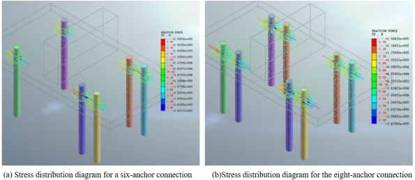
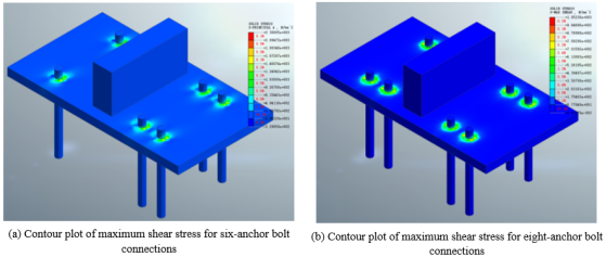
The results indicate that increasing the number of anchor bolts enhances the reinforcement effect of the steel anchor seat and reduces stress concentration in the concrete; however, the rate of increase in load-bearing capacity gradually slows down. The improvement achieved with 8 anchor bolts compared to 6 is minimal, and an excessive number of anchor bolts can also increase construction difficulty and costs.
Figure 12. Simulation results of the anchor bolt under load.
Figure 13. Simulation results for the anchor-concrete connection model.
5.2. Analysis of the Effect of Anchor Bolt Diameter on Anchoring Performance
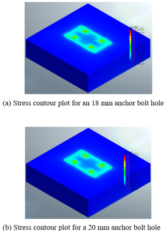
Based on the estimated concrete strength values from the project, finite element models YJ-D18-4-1 and YJ-D20-4-1 were established, with the positions and lengths (200 mm) of the anchor bolt holes remaining unchanged.
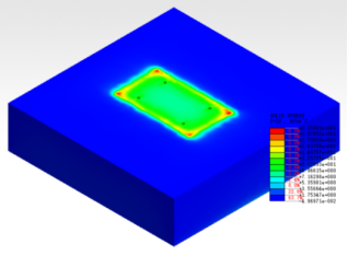
Figure 14. Stress contour plot of anchor bolt holes in concrete substrates.
The increase in the number of anchor bolts and the increase in the diameter of anchor bolts have an impact on the anchoring performance. The ultimate bearing capacity increases with the increase in the number of anchor bolts and the increase in the diameter of anchor bolts, but the rate of increase is gradually slow. The 20 mm anchor bolt has only a slight increase compared with the 18 mm anchor bolt, and it is easy to cause concrete hole wall extrusion cracking; the optimal design parameters are obtained by comprehensive analysis: 16mm diameter, 6 anchor bolts, buried depth of 6.5D ~ 10D, combined with anchor glue composite anchorage. The combination has sufficient bearing capacity, uniform stress and good durability, and can be directly used in engineering design.
6. Conclusions
The failure mechanism of chemical anchors is primarily conical-adhesive composite failure. The load-bearing capacity increases non-linearly with embedment depth, but the rate of increase slows after 8D. For 16-mm anchors, the safety factor meets engineering requirements when the embedment depth is between 6.5D and 10D; large-diameter anchors exhibit lower bonding efficiency;
Anchoring adhesives can effectively enhance the initial stiffness of steel anchor sockets. The average failure load for specimens using pure anchoring adhesive was 159.5 kN, and the uniformity of adhesive application is the key factor affecting its bonding performance; The average failure load of the chemical anchor-adhesive composite anchoring system was 309.0 kN, representing a 93.7% increase over the pure adhesive system. The failure mode was adhesive cracking combined with anchor shear failure; uneven stress distribution in the anchor was a major cause of system failure;
The average error between the derived theoretical formulas for the three core bearing capacity categories and the experimental values was less than 6.2%. The relative error between the finite element simulation results and the experimental values was 5.3%. Both the theoretical and numerical models demonstrate high accuracy and can accurately predict the mechanical performance of the composite anchoring system;
The number of anchor bolts has a far greater impact on anchoring performance than their diameter. The optimal design parameters are six 16-mm-diameter anchor bolts with an embedment depth of 6.5D to 10D. This configuration yields a ultimate bearing capacity of 356.8 kN, with an average load of 59.5 kN per bolt, ensuring ample safety margin, uniform load distribution, and ease of construction.
Acknowledgments
The successful completion of this study is inseparable from the strong support of colleagues. Here, I offer my most sincere thanks. First of all, we sincerely thank the guidance experts for their careful guidance throughout the research process, from experimental design, theoretical derivation, to thesis writing, all of which have given accurate thinking guidance and methodological guidance. At the same time, we also appreciate the assistance provided by the laboratory team to ensure the smooth development of the tests. Finally, I would like to thank the relevant units that provided support for this study and the experts who put forward valuable opinions in the process of paper review. The results of this study have gathered the efforts of all people, and express our sincere thanks to all the individuals and units who have given help and support!
Author Contributions
Liya Pei: Conceptualization, Methodology, Investigation, Project administration, Writing – original draft
Jun Song: Supervision, Formal Analysis
Jifeng Wen: Resources, Software
Peng Kang: Project administration
Jing Huang: Writing – review & editing
Funding
This work is not supported by any external funding.
Data Availability Statement
The data supporting the outcome of this research work has been reported in this manuscript.
Conflicts of Interest
The authors declare no conflicts of interest.
References
| [1] |
Hu C Z, Song C Y. Experimental research on external prestressed CFRP plate strengthening of existing concrete T-beams [J]. Journal of China & Foreign Highway, 2025, 45(2): 118-124.
https://doi.org/10.14048/j.issn.1671-2579.202502022
|
| [2] |
Zhang K, Huang S. Research on anchorage design optimization for external prestressing reinforcement of highway bridge based on JTG/T J23 specification [J]. World Bridges, 2023, 51(5): 78-83.
https://doi.org/10.3969/j.issn.1671-8437.202305015
|
| [3] |
Cook, R. A., Doerr, G. T., Klingner, R. E. Bond stress model for design of adhesive anchors. ACI Structural Journal. 1993, 90(5), 514–524.
https://doi.org/10.14359/51626427
|
| [4] |
Cook, R. A., Kunz, J., Fuchs, W., Konz, R. C. Behavior and design of single adhesive anchors under tensile load in uncracked concrete. ACI Structural Journal. 1998, 95(1), 9–25.
https://doi.org/10.14359/522
|
| [5] |
Cook, R. A. Behavior of chemically bonded anchor. Journal of Structural Engineering. 1993, 119(9), 2744–2762.
https://doi.org/10.1061/(ASCE)0733-9445(1993)119:9(2744)
|
| [6] |
Burton C, Visintin P, Griffith M C. Laboratory investigation of pull-out capacity of chemical anchors in individual new and vintage masonry units under quasi-static, cyclic and impact load [J]. Structures, 2021, 34: 901-930.
https://doi.org/10.1016/j.istruc.2021.08.016.
|
| [7] |
Wu, G., Wu, Z. S., Wei, Y., et al. Theoretical Analysis of Prestressed High-Strength Steel Wire Rope for Flexural Reinforcement of Reinforced Concrete Beams. Journal of Civil Engineering. 2007, 40(12), 28–37.
https://doi.org/10.15951/j.tmgcxb.2007.12.005
|
| [8] |
Yu X R, Khodadadi N. Computational intelligence model for predicting the compressive strength of FRP-confined concrete column [J]. Structural Concrete,2025,26(3):1721-1738.
https://doi.org/10.1002/suco.70374
|
| [9] |
Meva, M., Cook, R. A., Krishnamurthy, K. Pullout simulation of post installed chemically bonded anchors. Journal of Structural Engineering. 1996, 122(9), 1016–1024.
https://doi.org/10.1061/(ASCE)0733-9445(1996)122:9(1016)
|
| [10] |
Zhang, H. W., Smith, S. T. FRP-to-concrete joint assemblages anchored with multiple FRP anchors. Composite Structures. 2012, 94, 403–414.
https://doi.org/10.1016/j.compstruct.2011.07.025
|
| [11] |
Qi Xiaoming, Lei Xu, Liu Xiaoyan, et al. Theoretical Analysis and Pull-out Test of Chemical Anchors for Concrete Substrate Bearing Capacity [J]. Journal of Changsha University of Science and Technology (Natural Science Edition), 2024, 21(2): 72-80.
https://doi.org/10.19951/j.cnki.1672-9331.20220920002
|
| [12] |
Giresini L, Puppio M L, Taddei F. Experimental pull-out tests and design indications for strength anchors installed in masonry/concrete under small spacing constraint [J]. Materials and Structures, 2023, 56(7): 129.
https://doi.org/10.1617/s11527-023-02197-9
|
| [13] |
Cook, R. A., Doerr, G. T., Klingner, R. E. Bond stress model for design of adhesive anchors. ACI Structural Journal. 1993, 90(5), 514–524.
https://doi.org/10.14359/51626427
|
Cite This Article
-
APA Style
Pei, L., Song, J., Wen, J., Kang, P., Huang, J. (2026). In-vitro Testing and Analysis of the Anchoring Capacity of Steel Anchor Plates in Chemical-Anchor-Based Prestressed Reinforcement. Journal of Civil, Construction and Environmental Engineering, 11(3), 80-92. https://doi.org/10.11648/j.jccee.20261103.13
 Copy
|
Copy
|
 Download
ACS Style
Pei, L.; Song, J.; Wen, J.; Kang, P.; Huang, J. In-vitro Testing and Analysis of the Anchoring Capacity of Steel Anchor Plates in Chemical-Anchor-Based Prestressed Reinforcement. J. Civ. Constr. Environ. Eng. 2026, 11(3), 80-92. doi: 10.11648/j.jccee.20261103.13
Copy
|
Download
AMA Style
Pei L, Song J, Wen J, Kang P, Huang J. In-vitro Testing and Analysis of the Anchoring Capacity of Steel Anchor Plates in Chemical-Anchor-Based Prestressed Reinforcement. J Civ Constr Environ Eng. 2026;11(3):80-92. doi: 10.11648/j.jccee.20261103.13
Copy
|
Download
-
@article{10.11648/j.jccee.20261103.13,
  author = {Liya Pei and Jun Song and Jifeng Wen and Peng Kang and Jing Huang},
  title = {In-vitro Testing and Analysis of the Anchoring Capacity of Steel Anchor Plates in Chemical-Anchor-Based Prestressed Reinforcement},
  journal = {Journal of Civil, Construction and Environmental Engineering},
  volume = {11},
  number = {3},
  pages = {80-92},
  doi = {10.11648/j.jccee.20261103.13},
  url = {https://doi.org/10.11648/j.jccee.20261103.13},
  eprint = {https://article.sciencepublishinggroup.com/pdf/10.11648.j.jccee.20261103.13},
  abstract = {To verify the reliability of the composite anchoring system consisting of chemical anchors and anchoring adhesive for the external prestressing reinforcement of concrete T-beams, this study conducted a systematic investigation through laboratory tests, theoretical derivations, and finite element simulations using MIDAS/FEANX. Tensile pull-out tests were designed using chemical anchors with three diameters (12, 16, and 20 mm) and five embedment depths ranging from 5D to 10D. Concurrently, tests were conducted on C50 concrete specimens to evaluate the bond strength at the adhesive interface and the composite anchorage capacity. Relevant theoretical formulas were derived, numerical models were established, and the failure modes and load differences were compared and analyzed. The results indicate that chemical anchors primarily exhibit a combined conical-adhesive failure mode. For 16 mm anchors with embedment depths ranging from 6.5D to 10D, the safety factor reaches 1.45 to 2.02. The anchoring adhesive increases the initial stiffness of the steel anchor seat by 42.6%, and the ultimate load-bearing capacity of the composite system is 93.7% higher than that of specimens using pure anchoring adhesive. The average error between the theoretically derived formula and experimental values was 5.8%, and the relative error between finite element simulation results and experimental values was 5.3%, both demonstrating high accuracy.},
 year = {2026}
}
Copy
|
Download
-
TY  - JOUR
T1  - In-vitro Testing and Analysis of the Anchoring Capacity of Steel Anchor Plates in Chemical-Anchor-Based Prestressed Reinforcement
AU  - Liya Pei
AU  - Jun Song
AU  - Jifeng Wen
AU  - Peng Kang
AU  - Jing Huang
Y1  - 2026/06/15
PY  - 2026
N1  - https://doi.org/10.11648/j.jccee.20261103.13
DO  - 10.11648/j.jccee.20261103.13
T2  - Journal of Civil, Construction and Environmental Engineering
JF  - Journal of Civil, Construction and Environmental Engineering
JO  - Journal of Civil, Construction and Environmental Engineering
SP  - 80
EP  - 92
PB  - Science Publishing Group
SN  - 2637-3890
UR  - https://doi.org/10.11648/j.jccee.20261103.13
AB  - To verify the reliability of the composite anchoring system consisting of chemical anchors and anchoring adhesive for the external prestressing reinforcement of concrete T-beams, this study conducted a systematic investigation through laboratory tests, theoretical derivations, and finite element simulations using MIDAS/FEANX. Tensile pull-out tests were designed using chemical anchors with three diameters (12, 16, and 20 mm) and five embedment depths ranging from 5D to 10D. Concurrently, tests were conducted on C50 concrete specimens to evaluate the bond strength at the adhesive interface and the composite anchorage capacity. Relevant theoretical formulas were derived, numerical models were established, and the failure modes and load differences were compared and analyzed. The results indicate that chemical anchors primarily exhibit a combined conical-adhesive failure mode. For 16 mm anchors with embedment depths ranging from 6.5D to 10D, the safety factor reaches 1.45 to 2.02. The anchoring adhesive increases the initial stiffness of the steel anchor seat by 42.6%, and the ultimate load-bearing capacity of the composite system is 93.7% higher than that of specimens using pure anchoring adhesive. The average error between the theoretically derived formula and experimental values was 5.8%, and the relative error between finite element simulation results and experimental values was 5.3%, both demonstrating high accuracy.
VL  - 11
IS  - 3
ER  -
Copy
|
Download