Review Article | | Peer-Reviewed

Comparison of Crack Measurement and FEM Analysis Using Infrared Camera for Concrete Surface of Coating-type Resin Sensor

Received: 5 January 2025     Accepted: 26 January 2025     Published: 17 February 2025
Views:       Downloads:
Abstract

Infrastructure safety inspections typically rely on visual inspections and hammering tests by inspectors. However, a significant challenge is the variability in inspection results due to differences in inspectors' technical expertise. To address this issue, we propose an inspection method and preventive work using a coating-type resin sensor combined with an infrared camera. The use of thermography as a nondestructive evaluation technique is increasingly popular for maintaining concrete structures. Most inspections only evaluate the locations and shapes of defects on surfaces. Yet, no method has been developed to assess the depth of defects. In our approach, infrared-reactive resin is applied, and thermographic images of the target area are captured sequentially. Temperature curves obtained at each pixel during the cooling process are analyzed using the Fourier transform to differentiate defect states in various parts of the temperature distribution. The temperature change correlates with the defect size. Approximately 5% aluminum powder is mixed into the applied gel resin; due to its specific gravity, it tends to concentrate in areas damaged by compression failure or float. This report discusses technologies for identifying defects and measuring their size in infrared-reactive resin. It examines the effectiveness of preventive measures to prevent the scattering and collapse of defects caused by structural degradation. This paper presents a concentric loading test on reinforced concrete columns confined by gel resin ties. Test variables include concrete compressive strength and FEM analyses, ranging from 232-244 N/mm2, both below and above the equipment hole that caused the defect, and a comparison with test specimens free of defects to measure the relationship.

Published in Journal of Civil, Construction and Environmental Engineering (Volume 10, Issue 1)
DOI 10.11648/j.jccee.20251001.13
Page(s) 27-35
Creative Commons

This is an Open Access article, distributed under the terms of the Creative Commons Attribution 4.0 International License (http://creativecommons.org/licenses/by/4.0/), which permits unrestricted use, distribution and reproduction in any medium or format, provided the original work is properly cited.

Copyright

Copyright © The Author(s), 2025. Published by Science Publishing Group

Keywords

Infrared Thermography, Non-destructive Inspection, Spalling Prediction, Reinforcement, Health Monitoring

1. Introduction
In Japan, there are a large number of infrastructure structures such as bridges and tunnels that were constructed during the period of high economic growth in the 1960s and are now more than 50 years old. It is predicted that by 2020, 30% of the 730,000 road bridges (over 2m) and 22% of the 11,000 tunnels will be more than 50 years old . However, bridges and other structures are still in use even after they have exceeded their useful life, and more frequent inspections and repairs will be required in the future to prevent the risk of collapse or destruction. When monitoring to ensure the soundness of structures, it is extremely important to constantly monitor deterioration and structural changes under long-term supervision, as detecting dangerous conditions as early as possible plays a major role in building a safe and secure society. Until now, safety inspections of infrastructure structures have been conducted within 50 years of construction, when safety is guaranteed. However, we have now reached a critical juncture in which we must consider how to ensure the safety of aging infrastructure structures beyond this period, and there is an urgent need to develop new monitoring technologies. It is considered important to quantify the currently used empirical evaluation methods such as "visual inspection" and "hammering inspection," and to further improve the efficiency (standardization, cost reduction, etc.) and reliability (Improved accuracy, automatic data evaluation, etc.) of "non-destructive inspection" such as X-ray transmission and magnetic flaw detection . However, we considered developing technology aimed at preventing concrete pieces from falling from the ceiling due to deterioration of the walls of concrete piers of bridges and the tiled walls of high-rise buildings, and especially the inner walls of tunnels. We developed technology that is not affected by measurement conditions using a relatively inexpensive infrared camera in the long wavelength range, and verified a method of measuring concrete cracks, defects, and wall lifting using a simple measurement method. Figure 1(a) shows a crack on a concrete wall, and Figure 1(b) shows a floating concrete wall. Unlike detection using a general IR camera, this is a new inspection method in that it does not require heating or cooling the measurement point as long as the diurnal temperature difference between day and night is 7°C or more, but there are many places on the Japan Sea side in winter where the diurnal temperature difference is 6°C or less. If the diurnal temperature difference is small, the temperature difference between the concrete surface and the atmosphere becomes small, making evaluation using IR thermal images, which require a temperature difference, difficult in principle. In this study, passive measurement is made possible by using image analysis technology with an original infrared-responsive gel resin sensor that mixes aluminum powder into a gel resin . When this resin sensor is applied to the surface of a concrete wall, the aluminum powder contained in the gel resin flows and concentrates inside the defect when a crack or other problem occurs. As a result, when the wall surface is kept warm by sunlight, the defect is highlighted due to the temperature difference between the infrared radiation of the aluminum powder and the atmosphere, making it possible to measure it with an infrared camera. Even if there is no thermal radiation from sunlight from the wall surface, it is possible to similarly discover the defect from the temperature difference with the wall surface due to the radiative cooling effect from the aluminum powder. On the other hand, there are reports that rainwater can seep in through defects in concrete structures and flow into the room, causing leaks and accelerating deterioration .
This gel-resin sensor flows into cracks and defects due to the difference in specific gravity between the resin and metal, so it also has the effect of repairing defects and preventing rainwater from entering. Therefore, this measurement method can be described as a measurement technology that both measures defects in concrete walls and takes preventive measures.
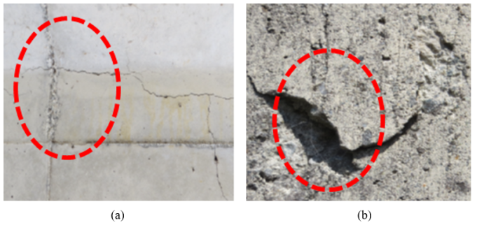
Figure 1. In this picture, concrete peeling and clacking are seen on the surface.
2. Measurement Technology Using for Coating Gel Resin Sensors
Infrared cameras are devices that convert the infrared energy they detect into pseudo-temperature data to create an image, and in recent years have been used to measure lifting and surface cracks caused by rebar corrosion inside reinforced concrete walls. Because infrared radiation energy is proportional to temperature, currently defects are detected by increasing the temperature difference by heating and cooling the measurement target using an external heat source. On the other hand, our research is to increase the temperature difference of the measurement object using gel resin and to reduce the cost of the measuring device by using a long-wavelength (8~12μm) infrared camera. Note that an example in the J-Stage, where infrared detection wavelengths have been put to practical use, 3-5 μm medium-wavelength infrared is used to evaluate soundness by processing images processed by software . However, this measurement device, including the software, costs approximately 20 million yen, and there are problems with it not being widely used for normal inspections.
2.1. Comparison with Conventional Measurement Technology
Various methods are used for quantitative measurement of the soundness of structures for the purpose of disaster prevention and mitigation. Sensor systems for measuring displacement and vibration due to static load include a method that uses a laser displacement meter or a contact displacement meter to measure displacement, and a method that uses a microtremor vibrator to measure natural vibrations and identify the state of destruction and stress concentration points by FEM analysis . Microtremor vibration measurement calculates the amplification characteristics and natural period of a structure by calculating the Fourier spectrum ratio of the vertical component to the horizontal component , and normalizing the horizontal vibration to the vertical vibration. A measurement unit consisting of a microtremor meter, data logger, and PC costs about 1.5 to 2.5 million yen. The laser Doppler velocimeter (LDV) method detects the velocity from the phase difference caused by the Doppler effect between the irradiated light and the reflected light when a laser beam is irradiated on the measurement target. The system consists of two LDV devices, a data logger, a PC, and a digital displacement meter, and costs around 4.5 to 6 million yen, which creates problems with diversification.
X-ray analysis using FEM is also used as a method to non-destructively and quantitatively evaluate residual stress in structures. Non-destructive X-ray equipment can be installed to monitor limited areas, but it is not practical for long-term measurements because it requires equipment costs of approximately 8 to 10 million yen and a power source, and it is difficult to perform crack progression analysis. Wall surface inspection techniques for structures using infrared cameras include a thermography method that uses the temperature difference caused by sunlight on the exterior walls of buildings, and measures differences in the conductivity of wall materials to measure differences in defective areas . In addition, a method to highlight damaged areas from infrared thermal images estimates the probability of damage prediction in temperature change areas based on image filtering and the features of the processed images . Furthermore, as a method for quantitatively evaluating the risk of spalling, a rebar corrosion expansion pressure simulation test using infrared thermography is performed on specimens at each damage stage, and the degree of deterioration is calculated without considering the cover or fracture form . Most of the time, the equipment is equipped with an InSb infrared sensor that detects mid-infrared rays (MWIR) from 3 to 5 μm, but there are also some equipped with sensors that detect far-infrared rays (LWIR) from 7.5 to 9.3 μm. However, since the equipment is equipped with a sensor that requires cooling, it is large and heavy, and since it requires a power source, it is difficult to mount it on a drone . It seems that long-term monitoring for more than 20 years is necessary to evaluate the safety and soundness of concrete structures. However, there are currently no measuring devices that can guarantee long-term monitoring or smart sensing methods that can even predict hazards . On the other hand, the Ministry of Land, Infrastructure, Transport and Tourism recommends using infrared cameras on drones to measure flying objects. Although there are problems with the measurement accuracy, it is expected that this will be used more frequently in the future due to personnel shortages caused by the declining birthrate and aging population .
2.2. Principles of Infrared Thermography
Most objects at room temperature emit energy through infrared radiation. Formula (1) shows Planck's law of radiation, and formula (2) shows Boltzmann's law, which states that all objects emit energy proportional to the fourth power of their absolute temperature . If the surface temperature of the measurement target is 40°C (absolute temperature T = 273+40 = 313 K), then formula (3) gives the wavelength λ = 2897÷313≒9.2. If the surface temperature of the measurement target is 40°C, it is considered that a device using a wavelength in the 9.2μm band is necessary as a measurement condition. In addition, IR camera exploration can measure up to 4 cm deep in the concrete surface. If the diurnal range difference between day and night is 7°C or more, it is very convenient because there is no need to heat or cool the measurement location, but in winter on the Sea of Japan side, there are many places where the diurnal range difference is less than 6°C. If the diurnal range difference is small, the temperature difference between the concrete surface and the atmosphere becomes small, and evaluation using IR thermal images, which requires temperature difference, may be difficult in principle. Most objects at room temperature emit energy through infrared radiation. Formula (1) shows Planck's law of radiation, and formula (2) shows Boltzmann's law, which states that all objects emit energy proportional to the fourth power of their absolute temperature . If the surface temperature of the measurement target is 40°C (absolute temperature T=273+40=313 K), then formula (3) gives the wavelength λ = 2897÷313≒9.2. If the surface temperature of the measurement target is 40°C, it is considered that a device using a wavelength in the 9.2 μm band is necessary as a measurement condition. In addition, IR camera exploration can measure up to 4 cm deep in the concrete surface. If the diurnal range difference between day and night is 7°C or more, it is very convenient because there is no need to heat or cool the measurement location, but in winter on the Sea of Japan side, there are many places where the diurnal range difference is less than 6°C. If the diurnal range difference is small, the temperature difference between the concrete surface and the atmosphere becomes small, and evaluation using IR thermal images, which requires temperature difference, may be difficult in principle.
2.3. Consideration of Conventional Technology
As shown in the image acquisition diagram by infrared thermal radiation in Figure 2, the infrared rays emitted from the measurement target are propagated according to formulas (4) to (6). According to the principle of infrared thermography, if there is not enough difference between the temperature of the air and the temperature of the test piece during infrared measurement, heating of the test piece must also be taken into consideration .
EλT=2hc2λ51ehc/λKT-1[W / (m2μm)](1)
Wλb: Black body spectral radiant emittance at wave length λ
c: Speed of light (3×10⁸ vm/sec)
h: Planck's constant (6.6×10⁻²⁷Js)
K: Boltzmann constant (1.38×10 -16 J/k)
t: Absolute temperature of blackbody (K)
T: Object Temperature
ε: Spectral radiant heat of the object
λ: Wavelength (m)
Wb=σt4[W/m2](2)
Wb: Integrating the wavelength from λ = 0 to λ=∞ from Planck's formula Black body spectral radiance 82 (W.SR-1.m2)
Σ: Boltzmann constant (5.7×10 W/m)
T: Absolute temperature of blackbody (K)
λmax=2897/T[μm](3)
1-ε×WTa(4)
ε×WT(5)
ε<1(6)
3. Reinforced Concrete Specimens and Measurement Methods
The infrared camera (InfRec R450: Nippon Avionics) used in this study and its specifications are shown in Figure 2 and Table 1. Figure 3 shows the measurement conditions of the compression fracture test of the reinforced concrete specimen using a loading test machine (Maximum load 5000 kN). The fracture test was performed using a loading test machine with a maximum load of 5000 kN, and the maximum load of approximately 2200 kN was gradually applied vertically from the top of the specimen, until the specimen was completely destroyed after approximately 20 minutes. Figure 4 shows the rebar skeleton of the reinforced concrete specimen (300 × 400 × 1000 mm). The specimen was made using ordinary concrete with a cover thickness of approximately 20 mm. In addition, the piezoelectric displacement sensors shown in Figure 5 were fixed to the four corners of the lower surface of the specimen with M12 bolts to a 5 mm thick steel plate at the bottom of the specimen. This sensor is designed to output autonomously at displacement gradients of 1/200 and 1/100, and does not require a power source for measurement . In addition, to determine the effect of the infrared camera measurement and the results of the destruction prevention work by using gel resin as a heat retaining agent on the surface of the test specimen, gel resin CY52-276 (Toray Dow) was applied to a thickness of approximately 0.2 mm on the front, back, left side, and right side of the test specimen, and compared with a test specimen with nothing applied and a test specimen with only gel resin. In addition, to evaluate the properties of the gel resin, test specimens applied with gel resin as it is and test specimens applied with aluminum-containing gel resin mixed with aluminum powder were also prepared.
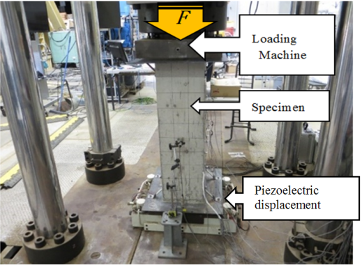
Figure 3. Structural drawing of the compressive loading machine and the specimen (300 × 400 × 10000 mm).
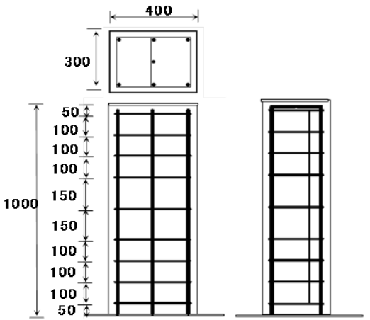
Figure 4. Experiment using equipment and specimens. (unit: mm).
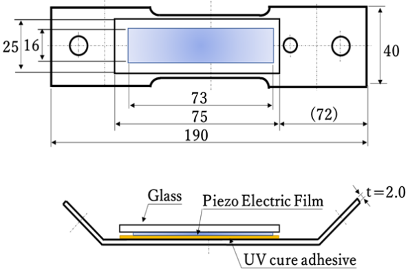
Figure 5. Details of shapes and dimensions of the piezoelectric displacement sensor.
Table 1. Infrared camera specifications.

Model

InfRec R450; Nippon Avionics Co., Ltd.

Detector

Two-dimensional non-cooling method

Measurement temperature range

-40 to 1500 °C

Measurement wavelength

8 to 14 μm

Number of pixels

480 × 360

Measurement field of view

24 deg × 18 deg

Standard lens

10 cm to ∞

Weight

3.8 kg

4. Measurement Considerations and Results
4.1. Comparison of Visible Light Camera Images and Infrared Camera Images of Specimen Destruction Due to Compression
Destructive tests were conducted on the reinforced concrete specimens shown in Figure 4. No pretreatment such as residual heat was performed during the destructive tests. In order to verify the effect of the gel resin on specimens of each shape, three types were created: (a) a specimen with nothing applied to the sides, (b) a specimen with the four sides coated with gel resin (no mixture), and (c) a specimen with the four sides coated with gel resin mixed with 5% aluminum powder. Visible light images and infrared images of each specimen after the maximum load had been applied are shown in Figure 6. In all specimens, the compressive force applied from above caused cracks and lifting in the specimens, and the results of measuring these cracks and lifting using thermal images from a visible light camera and an infrared camera are compared.
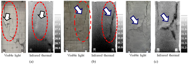
Figure 6. Comparison of visible light and infrared images with and without resin coating of specimens a, b, and c.
4.2. Displacement Due to Load on Test Specimen and FEM Analysis
Figure 7(a) shows the relationship between the applied force and the displacement without the gel resin applied, with the broken line. The solid line is the output state of the original piezoelectric displacement sensor. This sensor is designed to output about 1000kN when the specimen is moderately damaged (displacement gradient is 1/200 displacement about 5 mm) and about 2200 kN when it is completely destroyed (displacement gradient is 1/100 displacement about 10 mm). The output displacement is about 5 mm and 12 mm, and there is a difference in the measurement from the set value. It is thought that there is no significant change due to the remaining strength of the specimen, so there is a delay in the output from the piezo, resulting in an error in the displacement value. The broken line shows the applied force value applied to the specimen. (b) shows the relationship between the applied force and the displacement when only the gel resin is applied to the front. The output points of the piezoelectric displacement sensor show displacements of about 5mm and 9.5mm, which are almost the design value. This was confirmed by the 5mm displacement output, which shows the beginning of destruction due to the applied force. The state of destruction was visually confirmed with little fragmentation due to decomposition of the test specimen, and the wrapping effect of the resin was evident. (c) 5% aluminum powder was mixed into gel resin and applied to the four surfaces of the test specimen. The onset of destruction was observed at a gradient of 1/200, 5 mm, as designed, as indicated by the displacement meter output, but at a gradient of 1/100, the displacement meter output was 11.5 mm. This result suggests that the wrapping effect of the resin has been further increased, preventing the test specimen from collapsing completely. In other words, the effectiveness of the preventive measures was also evident. (d) shows the destruction state of the test specimen as calculated numerically. The maximum applied force was 2500 kN (measured value was 2200 kN), with a displacement of 9.5 mm.
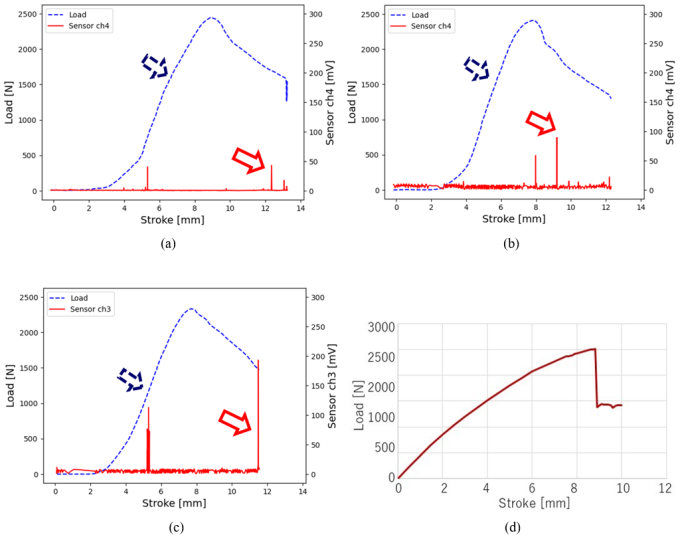
Figure 7. Relationship between load and displacement use a piezoelectric displacement sensor and simulation.
Figure 8 shows, the analysis was performed using ATENA 3D (version 5.9.1.21517), a nonlinear finite element analysis software specifically designed for simulating the behavior of concrete and reinforced concrete structures. The model was constructed using quadrilateral elements with a basic mesh size of 100 mm per side. Around the openings, the circular geometry was approximated with hexagonal meshes to ensure proper fitting. The analysis model consisted of three-dimensional nonlinear solid elements equipped with specialized tools for reinforced concrete structures. For boundary conditions, the specimen base was fixed, and distributed loads were applied as loading conditions to the upper surface. The analysis employed the Newton-Raphson method, with displacement increments of 0.5 mm from 0 mm to 8 mm displacement, followed by finer increments of 0.1 mm from 8 mm to 10 mm displacement to evaluate the progression of strain and crack development. The FEM analysis diagram in Figure 8(a) shows the destruction of the specimen at a gradient of 1/200 and a displacement of about 5 mm, and it was difficult to judge because no significant destruction was shown. However, the FEM analysis diagram in (b) at a displacement of 8.8 mm shows a state diagram in which a load of about 2200 kN is applied to the specimen structure. The strength of the specimen structure is affected from the center of the specimen structure, and the rebar breaks. This is shown in light green in the FEM analysis diagram. (c) is a diagram of the specimen in the FEM analysis diagram at a displacement of 9.5 mm when a load of about 2200 kN is applied. This shows a state in which the load is concentrated in the center of the specimen, causing significant damage. (d) shows that the destruction has progressed further and is in its final state. The load is 2500 kN, the gradient is 1/100, and the displacement is 10 mm.
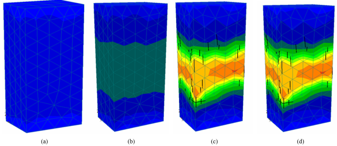
Figure 8. FEM analysis results of test specimen (a) because of load and displacement.
4.3. Knowledge Obtained from This Experiment
The gel resin applied to the test specimen has a certain hardness and heat retention properties that do not deteriorate or undergo chemical changes over time. This property also prevents fragments from scattering or falling due to breakage, as the elasticity of the gel resin increases when it settles on the surface after application. The application of gel resin is also thought to be effective in preventing collapses in tunnels and deterioration of fallen objects such as concrete bridge piers over time. It is also thought that its uses can be expanded to include scattering of window glass fragments during earthquakes and disasters. However, further measurement results and reliability must be compiled to confirm its effectiveness. For example, it may be necessary to compare the measurement performance using two infrared cameras with different wavelengths and develop technology to measure the depth of cracks.
5. Conclusion
The following findings were obtained through this measurement technology.
(1) To improve the resolution of long-wavelength infrared thermal images, the temperature difference with the outside air must be large, and the difference must be at least 0.7°C.
(2) Due to the effect of the gel resin applied to the surface of the test piece, even if the temperature inside the test piece is lower than the outside air temperature, the radiant heat difference from the broken part can be maintained large, and a clear infrared thermal image of the damaged part can be obtained. In theory, a difference between the internal temperature and the outside air temperature of about 5°C is required for measurement using only gel resin, but by using gel resin mixed with aluminum powder, a temperature difference of less than 1°C is possible.
(3) Compared to the medium-wavelength 3-5μm infrared camera used in the infrared thermal image measurement of the J system, the gel resin coating makes the long-wavelength 8-14μm infrared camera uncooled, inexpensive, has a wide measurement range, and can obtain results suitable for measuring "peeling" and "floating". It also has the effect of preventing the progression of shear and surface peeling during destruction, and is thought to be promising as a construction method to prevent rubble from falling.
(4) As can be seen from the FEM analysis, the force applied from above is concentrated in the center of the test specimen, so in order to prevent cracks in the structure and corrosion of the reinforcing bars, it is important to prevent rainwater from entering. The applied resin is thought to prevent rainwater from entering through the cracks and corrosion and deterioration of the reinforcing bars.
In the future, we would like to develop health monitoring technology using installed sensors, this measurement system, and the close-proximity measurement technology of a wall-climbing robot.
Abbreviations

IR

Infrared

FEM

Finite Element Method

LDV

Laser Doppler Velocimeter

MWIR

Medium Wavelength Infrared Detector

LWIR

Long-wavelength Infrared Radiation

Author Contributions
Nobuhiro Shimoi: Writing original draft, Measurements Conceptualization, Data curation, Formal Analysis, Investigation, Resources, Supervision
Kazuhisa Nakasho: Writing original draft, measurements, Formal analysis, Visualization, Software, Investigation, Supervision
Yu Yamauchi: Writing original draft, measurements, Validation, Investigation, Visualization
Conflicts of Interest
The authors declare no conflicts of interest.
References
[1] Ministry of Land, Infrastructure, & Transport. Infrastructure maintenance information. Available from
[2] Matsuoka, H., Hirose, Y., Kurahashi, T., Murakami, Y., Toyama, S., Ikeda, H., Iyama, T. & Ihara, I, (2018), Application of a joint variable method for high accurate numerical evaluation of defect based on hammering test. Journal of the Society of Materials Science, Vol. 67, No. 9, pp. 869-876. (in Japanese).
[3] Infrared Temperature Analysis Using Lock-in Method, JFE Techno-Research Corporation,
[4] Seki, K., Iwasa, K. & Tsutsumi, H., (2022), A Study on the Differences in the Judgment Results of Sound Hummering Inspection in the Diagnosis of RC Exterior Walls and Its Improvement by New Technology, Journal of infrastructure maintenance research Vol. 1, No. 1, pp. 394-401, (in Japanese).
[5] Shimoi, N., Yamauch, Y. & Nakasho, K., (2023), Preventive Work and Health Monitoring for Technology by Cracks of Concrete Surface Using Coating Type Resin Sensor, International Journal of Sensors and Sensor Networks. Vol. 11, No. 1, pp. 1-10.
[6] Yoshida, M., Yamada, S., Funami, Y. & Nakamura, H., (2021), Attempt to Measure Boiling Heat Transfer Fluctuation through a Visible-light Transparent Heater by Infrared Thermography, Transactions of the Japan Society of Refrigerating and Air Conditioning Engineers, Vol. 38, No. 2, pp. 145-152, (in Japanese).
[7] Ueda, H., Ushijima, S. & Shyutto, K., (2007), Properties and deterioration prediction of acid attacked concrete. Japan Society of Civil Engineers, Vol. 63 No. 1, pp. 27-41 (in Japanese).
[8] West Nippon Expressway Company Limited., (2022), J-system,
[9] Tamai, H. (2003), Elasto-Plastic Analysis Method for frame with exposed-type column base considering influence of variable axial force, Journal of Structural and Construction Engineering, Vol. 68, No. 571, pp. 127-135 (in Japanese).
[10] Shimoi, N., Nishida, T., Obata, A., Nakasho, K., Madokoro, H. & Cuadra, C., (2016), Comparison of displacement measurements in exposed type column base using piezoelectric dynamic sensors and static sensors, American Journal of Remote Sensing, Vol. 4, No. 5, pp. 23-32. (in Japanese).
[11] Nagao, T., Yamada, M. & Nozu, A., (2010), A study on the empirical evaluation method of site amplification effects by use of microtremor H/V spectrum, Journal of structural engineering A, Vol. 56A, pp. 324-333 (in Japanese).
[12] Miyashita, T., Ishii, H., Fujino, Y., Shoji, T. & Seki, M. (2007), Understanding of high-speed train induced local vibration of a railway steel bridge using laser measurement and its effect by train speed, Japan Society of Civil Engineering A, Vol. 63, No. 2, pp. 277-296 (in Japanese).
[13] Suzuki, T., Otaka, N., Fujimoto, Y., Shimamoto, Y. & Asano, I., (2019), Detection and Evaluation of Corroded Conditions in Steel Sheet Pile Using Infrared Images with UAV, Journal of the Japanese Society of Irrigation, Drainage and Rural Engineering, Vol. 87, No. 8, pp. 659-662, (in Japanese).
[14] Seki, K., Yamaguchi, A. & Kubota, S., (2021), Bridge Inspection Field Support and Inspection Method by Heat Map Using 3D Point Cloud Data in Japan, 38 th International Symposium on Automation and Robotics in Construction (ISARC 2021), pp. 161-168.
[15] Michimura, K., (2008), Deterioration diagnosis technology by infrared method, Material Life Society, Vol. 20, No. 1, pp. 21-26 (in Japanese).
[16] Hayashi, H., Hashimoto, K. & Akashi, Y., (2013), Improving detection accuracy of concrete damage by infrared thermography, Japan Concrete Institute, Vol. 35, No. 1, pp. 1813-1818 (in Japanese).
[17] Nakamura, S., Takaya, S., Maeda, Y., Yamamoto, T. and Miyagawa, T., (2013), Spalling time prediction by using infrared thermography, Japanese Journal of JSCE E2, Vol. 69, No. 4, pp. 450-461 (in Japanese).
[18] Sakagami, T. (2022), Application of drone-mounted infrared equipment to the architectural field and other fields about applicability, The Japan Building Disaster Prevention Association, Vol. 534, pp. 31-36 (in Japanese).
[19] Nakamura., M. (2002), Health monitoring of building structures, Society of Instrument and Control Engineers, Vol. 41, No. 11, pp. 819-824 (in Japanese).
[20] Ono., K. (2003) Study on technology for extending the life of structures, New urban society technology fusion research, The Second New Urban Social Technology Seminar, pp. 11-23 (in Japanese).
[21] Kumagai, K., Nakamura, H. & Kobayashi, H., (1999), Computer aided nondestructive evaluation method of welding residual stresses by removing reinforcement of weld, Transactions of the Japan Society of Mechanical Engineers, Series A, Vol. 65, No. 629, pp. 133-140 (in Japanese).
[22] Miyauchi, H., (2022), Infrastructure development of drone in the architectural field and utilization of drone for building inspection, Technical Journal of Advanced Mobility, Vol. 3, No. 3, pp. 27-42 (in Japanese).
[23] Shimizu, K., (1987), The latest technology for far-infrared use, Industrial Technology Association, pp. 6-24 (in Japanese).
[24] Maldague, X., (2002), Introduction to NDT by active infrared thermography, Materials Evaluation, pp. 1-22.
[25] Shimoi, N., Nakasho, K. & Yamauchi, Y., (2022), Development of Measurement and Preventive Work for Technology by Cracks of the Concrete Surface Using Coating Type Resin for Infrared Images Processing, The Tenth Japan Conference on Structural Safety and Reliability, pp. 72-78 (in Japanese).
Cite This Article
  • APA Style

    Shimoi, N., Nakasho, K., Yamauchi, Y. (2025). Comparison of Crack Measurement and FEM Analysis Using Infrared Camera for Concrete Surface of Coating-type Resin Sensor. Journal of Civil, Construction and Environmental Engineering, 10(1), 27-35. https://doi.org/10.11648/j.jccee.20251001.13

    Copy | Download

    ACS Style

    Shimoi, N.; Nakasho, K.; Yamauchi, Y. Comparison of Crack Measurement and FEM Analysis Using Infrared Camera for Concrete Surface of Coating-type Resin Sensor. J. Civ. Constr. Environ. Eng. 2025, 10(1), 27-35. doi: 10.11648/j.jccee.20251001.13

    Copy | Download

    AMA Style

    Shimoi N, Nakasho K, Yamauchi Y. Comparison of Crack Measurement and FEM Analysis Using Infrared Camera for Concrete Surface of Coating-type Resin Sensor. J Civ Constr Environ Eng. 2025;10(1):27-35. doi: 10.11648/j.jccee.20251001.13

    Copy | Download

  • @article{10.11648/j.jccee.20251001.13,
      author = {Nobuhiro Shimoi and Kazuhisa Nakasho and Yu Yamauchi},
      title = {Comparison of Crack Measurement and FEM Analysis Using Infrared Camera for Concrete Surface of Coating-type Resin Sensor
    },
      journal = {Journal of Civil, Construction and Environmental Engineering},
      volume = {10},
      number = {1},
      pages = {27-35},
      doi = {10.11648/j.jccee.20251001.13},
      url = {https://doi.org/10.11648/j.jccee.20251001.13},
      eprint = {https://article.sciencepublishinggroup.com/pdf/10.11648.j.jccee.20251001.13},
      abstract = {Infrastructure safety inspections typically rely on visual inspections and hammering tests by inspectors. However, a significant challenge is the variability in inspection results due to differences in inspectors' technical expertise. To address this issue, we propose an inspection method and preventive work using a coating-type resin sensor combined with an infrared camera. The use of thermography as a nondestructive evaluation technique is increasingly popular for maintaining concrete structures. Most inspections only evaluate the locations and shapes of defects on surfaces. Yet, no method has been developed to assess the depth of defects. In our approach, infrared-reactive resin is applied, and thermographic images of the target area are captured sequentially. Temperature curves obtained at each pixel during the cooling process are analyzed using the Fourier transform to differentiate defect states in various parts of the temperature distribution. The temperature change correlates with the defect size. Approximately 5% aluminum powder is mixed into the applied gel resin; due to its specific gravity, it tends to concentrate in areas damaged by compression failure or float. This report discusses technologies for identifying defects and measuring their size in infrared-reactive resin. It examines the effectiveness of preventive measures to prevent the scattering and collapse of defects caused by structural degradation. This paper presents a concentric loading test on reinforced concrete columns confined by gel resin ties. Test variables include concrete compressive strength and FEM analyses, ranging from 232-244 N/mm2, both below and above the equipment hole that caused the defect, and a comparison with test specimens free of defects to measure the relationship.
    },
     year = {2025}
    }
    

    Copy | Download

  • TY  - JOUR
    T1  - Comparison of Crack Measurement and FEM Analysis Using Infrared Camera for Concrete Surface of Coating-type Resin Sensor
    
    AU  - Nobuhiro Shimoi
    AU  - Kazuhisa Nakasho
    AU  - Yu Yamauchi
    Y1  - 2025/02/17
    PY  - 2025
    N1  - https://doi.org/10.11648/j.jccee.20251001.13
    DO  - 10.11648/j.jccee.20251001.13
    T2  - Journal of Civil, Construction and Environmental Engineering
    JF  - Journal of Civil, Construction and Environmental Engineering
    JO  - Journal of Civil, Construction and Environmental Engineering
    SP  - 27
    EP  - 35
    PB  - Science Publishing Group
    SN  - 2637-3890
    UR  - https://doi.org/10.11648/j.jccee.20251001.13
    AB  - Infrastructure safety inspections typically rely on visual inspections and hammering tests by inspectors. However, a significant challenge is the variability in inspection results due to differences in inspectors' technical expertise. To address this issue, we propose an inspection method and preventive work using a coating-type resin sensor combined with an infrared camera. The use of thermography as a nondestructive evaluation technique is increasingly popular for maintaining concrete structures. Most inspections only evaluate the locations and shapes of defects on surfaces. Yet, no method has been developed to assess the depth of defects. In our approach, infrared-reactive resin is applied, and thermographic images of the target area are captured sequentially. Temperature curves obtained at each pixel during the cooling process are analyzed using the Fourier transform to differentiate defect states in various parts of the temperature distribution. The temperature change correlates with the defect size. Approximately 5% aluminum powder is mixed into the applied gel resin; due to its specific gravity, it tends to concentrate in areas damaged by compression failure or float. This report discusses technologies for identifying defects and measuring their size in infrared-reactive resin. It examines the effectiveness of preventive measures to prevent the scattering and collapse of defects caused by structural degradation. This paper presents a concentric loading test on reinforced concrete columns confined by gel resin ties. Test variables include concrete compressive strength and FEM analyses, ranging from 232-244 N/mm2, both below and above the equipment hole that caused the defect, and a comparison with test specimens free of defects to measure the relationship.
    
    VL  - 10
    IS  - 1
    ER  - 

    Copy | Download

Author Information
  • Faculty of Systems Science and Technology, Akita Prefectural University, Yurihonjo, Japan

    Biography: Nobuhiro Shimoi is a professer at Department of Intelligent Mechatronics, Faculty of Systems Science and Technology, Akita Prefectural University. He earned his Ph.D in engineering from the Graduate School of Engineering, National University of Shinshu in 1996. Recognized for his exceptional contributions, Ph.D. Shimoi has been honored with the senior members designation by the es-teemed Institute of Electrical and Electronics Engineers (IEEE). In addition, he holds a Minister of Education, Culture, Sports, Science and Technology Award Science and Technology Award, and Japan Society of Mechanical Engineers Medal for Technical Achievement Award. He has participated in multiple international research col-laboration projects for mine detecting technologies.

  • Graduate School of Sciences and Technology for Innovation, Yamaguchi University, Ube, Japan

    Biography: Kazuhisa Nakasho is an Associate Professor in the Division of Information and Engineering at Yamaguchi University's Graduate School of Sciences and Technology for Innovation. He received his B.S. degree from Kyoto University's Faculty of Science in 2001, and his M.S. degree in Mathematics from Kyoto University's Divi-sion of Mathematics and Mathematical Science in 2003. After working at Elysium Co., Ltd. as Development Manager, he received his Ph.D. in Engineering from Shinshu University in 2016. He then served as a Specially Appointed Assistant Professor at Akita Pre-fectural University and as an Assistant Professor at Osaka Univer-sity's Graduate School of Engineering. Since 2018, he has been with Yamaguchi University, where his research focuses on mathe-matical knowledge management, software implementation, and social implementation.

  • Faculty of Systems Science and Technology, Akita Prefectural University, Yurihonjo, Japan

    Biography: Yu Yamauchi is an Assistant Professor in the Department of Ma-chine Intelligence and Systems Engineering, Faculty of Systems Science and Technology, Akita Prefectural University. He received his Ph.D. in Information Science from Tohoku University in 2022. His research interests include robotics, fluid power systems, and infrastructure inspection. Currently, he is focusing on developing a wall-climbing robot equipped with an infrared camera for infra-structure inspection.