Abstract
The connection between a photovoltaic array and a load is still an interest subject of research. The impedance matching between a PV array and a load is a technological problem that basically means the maximum power transfer from a PV panel to a load. Although there are many works devoted to the problem of the maximum power point tracking (MPPT) in a PV array, only few of them deal with the nature of the power interface while most of them focus on different types of tracking algorithms. The problem is addressed in this study by a systemic approach from a power interface point of view in order to obtain high levels of efficiency, reliability and flexibility. Moreover, the simulations and experimental results prove that the proposed system gives a fast response and is suitable for rapidly changing weather conditions. In steady state, the tracking of the maximum power point with the proposed system is very effective or efficient and the quality of the signals is substantially improved. In addition, the output power fluctuation is also reduced, which is a major problem in all MPPT maximum power point trackers and especially the traditional ones, and reducing the output power fluctuation is a goal. adapting it to the load.
Keywords
Photovoltaic Generator, Solar Cells, MPPT, Simulation, Extreme Control, Optimization
1. Introduction
It is universally accepted that energy plays a central role in the development and economic growth of a country. Without energy, the world could not have reached the current level of development. Indeed, man, machines and nature all need it; therefore, the production of this energy is a challenge of great importance for the present and the future.
In the 21st century, debates on the planet's energy future have intensified given the ever-increasing needs in the field and the consequences that this may have in the medium and long term. Demographic change and industrial development suggest a considerable increase in energy consumption. At this rate, fossil fuel reserves will only be able to meet needs for a few more decades. Deposits of energy resources of fossil origin, even if they offer a short- and medium-term solution, pose real environmental problems linked to the treatment of radioactive waste and the dismantling of obsolete nuclear power plants. The still high price of oil, the ever more worrying degree of pollution, particularly greenhouse gas emissions, contrast with the new sustainable development provisions and make alternative and renewable energy sources increasingly attractive to which it is hard to give up.
By renewable energy, we mean energy from the sun, wind, heat from the earth, water or even biomass. Unlike fossil fuels, renewable energies are clean energies with unlimited and easily exploitable resources. These different sources offer inexhaustible and easily exploitable energy
| [4] | Boubii, C., Kafazi, I. E., Bannari, R., El Bhiri, B., Bossoufi, B., Kotb, H. & Nasiri, B. (2024). Synergizing Wind and Solar Power: An Advanced Control System for Grid Stability. Sustainability, 16(2), 815. |
| [12] | F. Bouchtouche Cherfa «Study and implementation of a photovoltaic power plant connected to the low-voltage electricity distribution network». Memory of magister, École National Polytechnique El-Harrach, 2004. |
[4, 12]
.
Solar panels generate electricity from sunlight, but the amount of energy they produce varies depending on factors such as temperature, shade and the angle of incidence of the sun. MPPT technology adjusts the electrical operating point of photovoltaic panels to ensure operation at the maximum power point, regardless of weather conditions. The power generated by GPV is an irregular energy source with major problems: low efficiency and non-linear output due to the intermittent nature of solar photovoltaic systems, such as variation in sunlight and temperature
| [1] | TAHIRI, F., HARROUZ, A., & BOSTANCI, G. E. (2024). AA comprehensive comparison of the two MPPT techniques (P&O, SMC) for photovoltaic systems. Algerian Journal of Signals and Systems, 9(1), 28-32. |
| [7] | Harrag, A., & Messalti, S. (2019). PSO‐based SMC variable step size P&O MPPT controller for PV systems under fast changing atmospheric conditions. International Journal of Numerical Modelling: Electronic Networks, Devices and Fields, 32(5), e2603. |
| [8] | Safari, A., & Mekhilef, S. (2010). Simulation and hardware implementation of incremental conductance MPPT with direct control method using cuk converter. IEEE transactions on industrial electronics, 58(4), 1154-1161. |
| [9] | N. Saïd: «Influence of temperature on electrical parameters, characteristics of polycrystalline silicon solar cells: modeling and analysis using infrared thermography», PhD Thesis from Aix-Marseille 3, 1986. |
| [10] | Mark Hankins «installations solaires photovoltaïques autonomes» Traduit de l’anglais par Daniel Gouadec, Ed Dunod, Paris 2012. |
[1, 7-10]
.
Thanks to the MPPT algorithm, the maximum power is obtained by the direct and indirect methods. Direct methods use the measured voltage and current of the PV array. We can cite: the disturbance and observation method (P&O), the incremental conductance method (IC), fuzzy logic (FL), artificial intelligence (AI), sliding mode control (SMC)
| [8] | Safari, A., & Mekhilef, S. (2010). Simulation and hardware implementation of incremental conductance MPPT with direct control method using cuk converter. IEEE transactions on industrial electronics, 58(4), 1154-1161. |
[8]
. These methods have the advantage of being autonomous with regard to PV characteristics such as temperature and radiation level during monitoring of the maximum power point. The indirect method influences the curve fitting, switching table utilization, open circuit voltage (VOC) and short circuit current (Icc)
| [9] | N. Saïd: «Influence of temperature on electrical parameters, characteristics of polycrystalline silicon solar cells: modeling and analysis using infrared thermography», PhD Thesis from Aix-Marseille 3, 1986. |
[9]
. Indirect techniques in the literature include artificial neural networks (ANN) and particle swarm optimization of a fuzzy logic controller (PSO-FLC)
| [1] | TAHIRI, F., HARROUZ, A., & BOSTANCI, G. E. (2024). AA comprehensive comparison of the two MPPT techniques (P&O, SMC) for photovoltaic systems. Algerian Journal of Signals and Systems, 9(1), 28-32. |
| [3] | Hichem, L., Leila, M., & Amar, O. (2024). The effectiveness of a hybrid MPPT controller based on an artificial neural network and fuzzy logic in low-light conditions. Bulletin of Electrical Engineering and Informatics, 13(3), 1453-1464. |
[1, 3].
In this work, different MPPT control strategies are studied and developed for the photovoltaic system to improve their efficiency. The MPPT P&O method algorithm encounters a serious problem such as oscillations at the maximum power point due to continuous disturbances which reduce its efficiency. In addition, it is very sensitive to changes in atmospheric conditions. To solve these problems, we improve the performance of the MPPT P&O controller by adding a proportional-integral (P.I) corrector.
This work will take place according to the following structure: an introduction, a presentation of the system, a methodology, modeling, simulation with its results and a conclusion.
2. Presentation of the PV System
An elementary solar cell is generally based on a simple PN junction. The qualitative and quantitative study of the solar cell is based on the simple Shockley model of a diode under darkness and under illumination. This model is sufficient to study the transport mechanisms of the cell and extract these main physical parameters
| [2] | Fergani, O. K. B. A., Mechgoug, R., Afulay Bouzid, A., Tkouti, N., & Mazari, A. (2024). A New Modified Bacterial Foraging MPPT Technique with Dynamic Mutation Rates for Photovoltaic Systems under Partial Shading Conditions. International Journal of Engineering, 37(8), 1569-1579. |
| [6] | Tchoketch Kebir, G. F., Larbes, C., Ilinca, A., Obeidi, T., & Tchoketch Kebir, S. (2018). Study of the intelligent behavior of a maximum photovoltaic energy tracking fuzzy controller. Energies, 11(12), 3263. |
| [9] | N. Saïd: «Influence of temperature on electrical parameters, characteristics of polycrystalline silicon solar cells: modeling and analysis using infrared thermography», PhD Thesis from Aix-Marseille 3, 1986. |
[2, 6, 9].
When a PN junction made from light-sensitive materials is illuminated, it has the particularity of being able to function as an energy generator. This static behavior can be described by the electrical equation defining the behavior of a classic diode
| [5] | BELHADJER, Y., Ait Abbas, H., Laroussi, K., Bousbaine, A., FERGANI, O., & Mazari, A. (2024). Optimizing DC Microgrid Systems for Efficient Electric Vehicle Battery Charging in Ain El Ibel, Algeria. International Journal of Engineering. |
| [11] | Labouret A, "Photovoltaic Solar Energy," Dunod, 3rd edition, Paris 2006. Ch1. |
[5, 11]
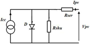
. Thus, the static electrical regime of a photovoltaic cell made up of a silicon PN junction can be described via the following equation:
Figure 1. Equivalent electrical diagram of a photovoltaic cell.
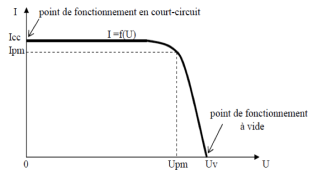
Figure 2. Current-voltage characteristic of a cell.
(1)
Photo-generated current:
(2)
Diode saturation current:
(3)
The gain of the PI controller by the Laplace transform:
The PI controller tuning parameters according to the Ziegler – Nichols method:
and(5)
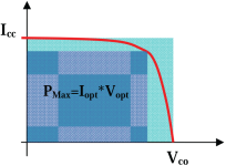
An important parameter is often used based on the I(V) characteristic to qualify the quality of a cell or PV generator: it is the factor form or fill factor (FF). It is illustrated in
Figure 3. This coefficient represents the ratio between the maximum power that the cell denoted Pmax can deliver and the power formed by the rectangle Icc * Vco. The greater the value of this factor, the greater the usable power. The best cells will therefore have been the subject of technological compromises to achieve the ideal characteristics as closely as possible
| [13] | Natural Resources and Growth: Economic and Political Issues Collected by the Organisation for Economic Co-operation and Development - OCDE 2009. |
| [15] | M. C. Alonso-Garcia, J. M. Ruiz, F. Chenlo, «Experimental study of mismatch and shading effects in the I-V characteristic of a photovoltaic module», Solar Energy Materials & Solar Cells Volume 90, Issue 3, 15 February 2006, Pages 329-340. |
[13, 15]
.
Figure 3. Concept of FF form factor for a photoelectric cell.
(6)
The most efficient cells are made with monocrystalline silicon, but the greatest quantity are made with multicrystalline obtained, most often, by molding in a silicon nitride or silica crucible. A charge of silicon made up of scrap from the production of crystals intended for the electronic component industry is melted, then gradually recrystallized by cooling the bottom of the crucible. The ensuing crystal growth is directional, the grains go from the bottom to the top of the ingot, deforming relatively little. This progressive solidification, which maintains contact with a solid phase and a liquid phase, develops a segregation of the impurities contained in the charge, which are drained towards the top of the molded ingot.
Depending on the technology, the photovoltaic cell can be monocrystalline, polycrystalline or amorphous.
3. Methodology
Firstly, we use the MPPT P&O to determine the maximum power point in the operation of the photovoltaic system, using the disturbance observation method. Then we improve the system by using a proportional-integral (P.I) corrector.
Models:
A PV module or field is characterized by its short circuit current Isc and its open circuit voltage.
(8)
For most cells, we can neglect the term in front Iph. The approximate expression for the short-circuit current is then:
The open circuit voltage is the voltage Vco for which the current delivered by the photovoltaic generator is zero. (This is the maximum voltage of a solar cell or photovoltaic generator).
(10)
In the ideal case, its value is slightly lower than:
With VT the thermal tension.
Photovoltaic modules are characterized by 2 main parameters: the current-voltage characteristic and the power-voltage characteristic.
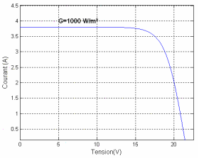
Figure 4. Current – voltage characteristic of a PV module.
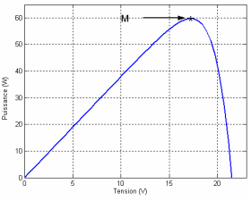
Figure 5. Power – voltage characteristic of a PV module.
Solar panels, although they are increasingly efficient, have yields that remain quite low
| [7] | Harrag, A., & Messalti, S. (2019). PSO‐based SMC variable step size P&O MPPT controller for PV systems under fast changing atmospheric conditions. International Journal of Numerical Modelling: Electronic Networks, Devices and Fields, 32(5), e2603. |
| [12] | F. Bouchtouche Cherfa «Study and implementation of a photovoltaic power plant connected to the low-voltage electricity distribution network». Memory of magister, École National Polytechnique El-Harrach, 2004. |
| [14] | M. Angel Cid Pastor «Design and production of electronic photovoltaic modules» PhD thesis from the National Institute of Applied Sciences of Toulouse, 2006. |
| [16] | A. Kajihara, T. Harakawa; «Model of photovoltaic cell circuits Under partial shading», Industrial Technology, 2005. ICIT 2005, 14-17 Dec. 2005 Page(s): 866-870. |
[7, 12, 14, 16]
. This is why we must exploit the maximum power they can generate while minimizing energy losses.
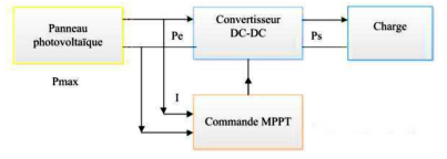
Figure 6. Block diagram of a MPPT search algorithm.
MPPT controls based on output current maximization are mainly used when the load is a battery. In all systems using output parameters, a power approximation (Pmax) is made through the converter efficiency. The better the conversion stage, the more valid this approximation is. However, all systems with a single sensor are inaccurate. Most of these systems were originally designed for space.
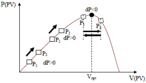
MPPT controls ultimately presenting a good compromise of static and dynamic efficiency but also robustness are based on a continuous evaluation of the power and a comparison with the state at the previous moment.
Figure 7. Operating principle of an MPPT command.
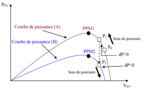
Also, the GPV can have its power curve modified at any time and therefore its maximum power point (MPP) as illustrated in the following figure. The operating point (P1) is on the rising part of the power curve (A) before the change in illumination. Following the variation in illumination, the operating point goes from P1 to P2 which is on the power curve (B). By comparing the power P2 and P1, we deduce a negative derivative, so we reverse the direction of pursuit thinking that we have exceeded the MPP, here the MPPT command momentarily loses the MPP. In addition, the change in the direction of pursuit moves the point of operation even further away from the MPP.
Figure 8. Change in lighting and consequence on the curves of power of a GPV as well as source-load adaptation.
3.1. Method MPPT P&O
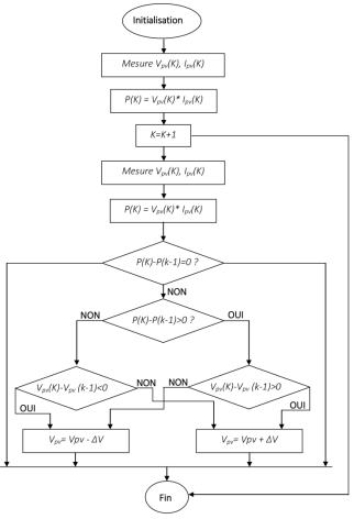
This method consists of disturbing one of the input parameters of the static converter (generally the voltage Vpv), and observing the impact of this change on the output power of the system, therefore all algorithms which contain an action of command associated with a search action are grouped under this name.
To explain the principle of this extremal control, starting from a control with a small duty cycle and at each cycle, by adjusting α regularly, Vpv and Ipv are measured in order to calculate P(K), the value obtained is compared with the value P(K-1) calculated in the previous cycle, according to this comparison, Vpv is adjusted either in the same direction as in the previous cycle or in an opposite direction. In this way, the power will then increase, return to the maximum, then decrease; upon detection of a reduction in power, the direction of the command is reversed again... Finally, the system oscillates around the maximum.
This oscillation allows the control system to check that the maximum has not moved and if necessary to follow it but it causes a loss of efficiency which increases with the incremental step of the disturbance, the average operating point being below the maximum. If this increment step is large, the MPPT algorithm responds quickly to sudden changes in operating conditions. The yield of this technique is approximately 85%.
The following figure represents the P&O method algorithm. The major disadvantage of this technique lies in the case of rapid change in atmospheric conditions.
Figure 9. P&O method algorithm.
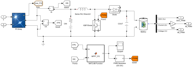
The following block diagram is used to perform the simulation in MATLAB Simulink.
Figure 10. MPPT P&O modeling block.
3.2. Method MPPT P&O + P.I.
The purpose of our work is to carry out a comparative study between two systems. One equipped with a classic MPPT controller which uses the P&O method (disturbance and observation) and the other equipped with an improved MPPT controller, which in addition to the P&O method, will be equipped with a P.I corrector (proportional - integral). These different studies will be carried out in a MATLAB/Simulink environment.
The simulation results of these comparison operations will be presented and analyzed at the end of this chapter. The different comparisons will be made at the output of the system and will make it possible to deduce which system is effective and efficient. We used the following control parameters in the commands:
Table 1. Control parameters.
Parameters | Symbols | Values |
Series resistance | Rs | 0,221 Ω |
Resistance in parallel | Rsh | 450 Ω |
Illumination intensity | G | 1000 W/m2 |
Rated temperature | Tn | 298 K |
The bandgap energy of the semiconductor | Eg0 | 1,1 eV |
Boltzmann constant | K | 1,38.10-23 J/K |
Electronic charge | q | 1,6.10-19 Coulomb |
The diode ideality factor | n | 1,3 |
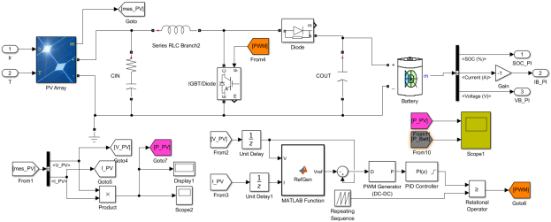
The following block diagram allows you to simulate the system in a Matlab Simulink environment using an improved MPPT P&O +P.I. regulator.
Figure 11. MPPT modeling block (P&O + PI).
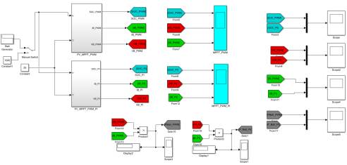
The comparative study of the two systems is carried out through the functional blocks in the Matlab/Simulink environment.
Figure 12. Comparative modeling block of the 2 methods.
Also, a spectral analysis by the F.F.T method of all the comparison signals is carried out. Thus, the most efficient and effective system will be determined.
4. Simulation and Results
The comparative study of the two systems provides the following results:
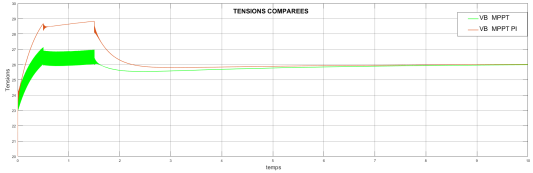
4.1. Comparative Battery Voltage Curves
Figure 13. Battery voltages compared.
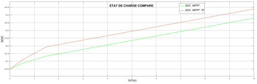
4.2. Comparative Curves of the States of Charge
Figure 14. State of charge of batteries compared.
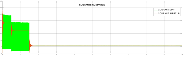
4.3. Comparative Battery Current Curves
Figure 15. Comparative graphs of battery currents.
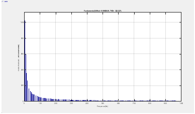
The spectral analysis by F.F.T, carried out in MATLAB Simulink, gives the following results:
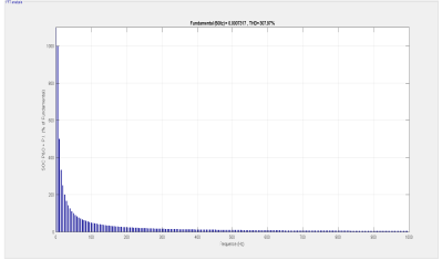
4.4. State of Charge
Figure 16. THD_SOC_MPPT P&O.
Figure 17. THD_SOC_MPPT P&O+P.I.
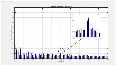
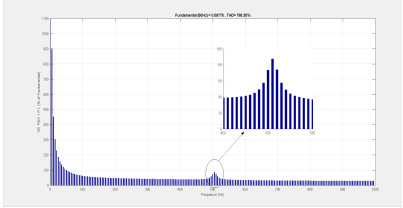
4.5. Voltage Battery
Figure 18. THD_VB_MPPT P&O.
Figure 19. THD_VB_MPPT P&O+P.I.
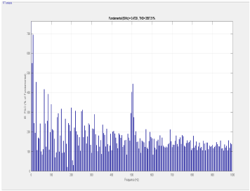
4.6. Current Battery
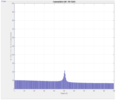
Figure 20. THD_IB_MPPT P&O.
Figure 21. THD_IB_MPPT P&O+P.I.
Also, from the spectral analysis carried out by the F.F.T in Matlab Simulink, we created the following table:
Table 2. Comparatives parameters.
| SOC THD (%) | VB THD (%) | IB THD (%) |
MPPT_P&O | 322.22 | 1340.77 | 3357.31 |
MPPT_P&O + P.I | 307.97 | 785.35 | 1724.53 |
4.7. Results Interpretation
A comparative analysis of the simulation results obtained shows that:
1) The oscillations around the MPPT for the P&O algorithm are much greater than with a P.I regulator integrated into the system;
2) The tracking time of the P.I regulator is faster than that of the P&O algorithm;
3) With the integrated P.I regulator, we have good tracking of the MPPT during rapid variations in illumination;
4) At constant illumination, the charging time of the storage system is faster with the P.I corrector than with the simple P&O algorithm;
5) The quality of the signals with the P.I corrector is always better than with the simple MPPT P&O regulator.
5. Conclusion
In this article, we presented a comparative study of the performance of a photovoltaic system between two MPPT control methods: MPPT P&O and MPPT P&O + P.I.
The simulation results show that the use of MPPT control makes it possible to considerably improve the efficiency of photovoltaic installations, as do the results obtained when inserting a proportional – integral regulator into an MPPT regulator. P&O, showed very good system response, superior signal quality as well as high performance.
Thus, the qualitative and quantitative performances of the system are all improved.
Abbreviations
PV | Photovoltaic |
Si | Silicium |
GPV | Photovoltaic Generator |
MPP | Maximum Power Point |
FF | Factor Form |
MPPT | Maximum Power Point Tracking |
CA | Alternating Current |
CC | Direct Current |
Conflicts of Interest
The authors declare no conflicts of interest.
References
| [1] |
TAHIRI, F., HARROUZ, A., & BOSTANCI, G. E. (2024). AA comprehensive comparison of the two MPPT techniques (P&O, SMC) for photovoltaic systems. Algerian Journal of Signals and Systems, 9(1), 28-32.
|
| [2] |
Fergani, O. K. B. A., Mechgoug, R., Afulay Bouzid, A., Tkouti, N., & Mazari, A. (2024). A New Modified Bacterial Foraging MPPT Technique with Dynamic Mutation Rates for Photovoltaic Systems under Partial Shading Conditions. International Journal of Engineering, 37(8), 1569-1579.
|
| [3] |
Hichem, L., Leila, M., & Amar, O. (2024). The effectiveness of a hybrid MPPT controller based on an artificial neural network and fuzzy logic in low-light conditions. Bulletin of Electrical Engineering and Informatics, 13(3), 1453-1464.
|
| [4] |
Boubii, C., Kafazi, I. E., Bannari, R., El Bhiri, B., Bossoufi, B., Kotb, H. & Nasiri, B. (2024). Synergizing Wind and Solar Power: An Advanced Control System for Grid Stability. Sustainability, 16(2), 815.
|
| [5] |
BELHADJER, Y., Ait Abbas, H., Laroussi, K., Bousbaine, A., FERGANI, O., & Mazari, A. (2024). Optimizing DC Microgrid Systems for Efficient Electric Vehicle Battery Charging in Ain El Ibel, Algeria. International Journal of Engineering.
|
| [6] |
Tchoketch Kebir, G. F., Larbes, C., Ilinca, A., Obeidi, T., & Tchoketch Kebir, S. (2018). Study of the intelligent behavior of a maximum photovoltaic energy tracking fuzzy controller. Energies, 11(12), 3263.
|
| [7] |
Harrag, A., & Messalti, S. (2019). PSO‐based SMC variable step size P&O MPPT controller for PV systems under fast changing atmospheric conditions. International Journal of Numerical Modelling: Electronic Networks, Devices and Fields, 32(5), e2603.
|
| [8] |
Safari, A., & Mekhilef, S. (2010). Simulation and hardware implementation of incremental conductance MPPT with direct control method using cuk converter. IEEE transactions on industrial electronics, 58(4), 1154-1161.
|
| [9] |
N. Saïd: «Influence of temperature on electrical parameters, characteristics of polycrystalline silicon solar cells: modeling and analysis using infrared thermography», PhD Thesis from Aix-Marseille 3, 1986.
|
| [10] |
Mark Hankins «installations solaires photovoltaïques autonomes» Traduit de l’anglais par Daniel Gouadec, Ed Dunod, Paris 2012.
|
| [11] |
Labouret A, "Photovoltaic Solar Energy," Dunod, 3rd edition, Paris 2006. Ch1.
|
| [12] |
F. Bouchtouche Cherfa «Study and implementation of a photovoltaic power plant connected to the low-voltage electricity distribution network». Memory of magister, École National Polytechnique El-Harrach, 2004.
|
| [13] |
Natural Resources and Growth: Economic and Political Issues Collected by the Organisation for Economic Co-operation and Development - OCDE 2009.
|
| [14] |
M. Angel Cid Pastor «Design and production of electronic photovoltaic modules» PhD thesis from the National Institute of Applied Sciences of Toulouse, 2006.
|
| [15] |
M. C. Alonso-Garcia, J. M. Ruiz, F. Chenlo, «Experimental study of mismatch and shading effects in the I-V characteristic of a photovoltaic module», Solar Energy Materials & Solar Cells Volume 90, Issue 3, 15 February 2006, Pages 329-340.
|
| [16] |
A. Kajihara, T. Harakawa; «Model of photovoltaic cell circuits Under partial shading», Industrial Technology, 2005. ICIT 2005, 14-17 Dec. 2005 Page(s): 866-870.
|
Cite This Article
-
APA Style
Diallo, M. A., Sow, D., Traore, S. D., Doumbia, I., Sanogo, C. O. (2026). Comparative Study of the Performances of a Photovoltaic System Using MPPT P&O and MPPT P&O+PI Controls. International Journal of Energy and Power Engineering, 15(1), 45-55. https://doi.org/10.11648/j.ijepe.20261501.14
 Copy
|
Copy
|
 Download
ACS Style
Diallo, M. A.; Sow, D.; Traore, S. D.; Doumbia, I.; Sanogo, C. O. Comparative Study of the Performances of a Photovoltaic System Using MPPT P&O and MPPT P&O+PI Controls. Int. J. Energy Power Eng. 2026, 15(1), 45-55. doi: 10.11648/j.ijepe.20261501.14
Copy
|
Download
AMA Style
Diallo MA, Sow D, Traore SD, Doumbia I, Sanogo CO. Comparative Study of the Performances of a Photovoltaic System Using MPPT P&O and MPPT P&O+PI Controls. Int J Energy Power Eng. 2026;15(1):45-55. doi: 10.11648/j.ijepe.20261501.14
Copy
|
Download
-
@article{10.11648/j.ijepe.20261501.14,
  author = {Mohamed Amadou Diallo and Demba Sow and Sibiri Datouma Traore and Issa Doumbia and Cheick Oumar Sanogo},
  title = {Comparative Study of the Performances of a Photovoltaic System Using MPPT P&O and MPPT P&O+PI Controls},
  journal = {International Journal of Energy and Power Engineering},
  volume = {15},
  number = {1},
  pages = {45-55},
  doi = {10.11648/j.ijepe.20261501.14},
  url = {https://doi.org/10.11648/j.ijepe.20261501.14},
  eprint = {https://article.sciencepublishinggroup.com/pdf/10.11648.j.ijepe.20261501.14},
  abstract = {The connection between a photovoltaic array and a load is still an interest subject of research. The impedance matching between a PV array and a load is a technological problem that basically means the maximum power transfer from a PV panel to a load. Although there are many works devoted to the problem of the maximum power point tracking (MPPT) in a PV array, only few of them deal with the nature of the power interface while most of them focus on different types of tracking algorithms. The problem is addressed in this study by a systemic approach from a power interface point of view in order to obtain high levels of efficiency, reliability and flexibility. Moreover, the simulations and experimental results prove that the proposed system gives a fast response and is suitable for rapidly changing weather conditions. In steady state, the tracking of the maximum power point with the proposed system is very effective or efficient and the quality of the signals is substantially improved. In addition, the output power fluctuation is also reduced, which is a major problem in all MPPT maximum power point trackers and especially the traditional ones, and reducing the output power fluctuation is a goal. adapting it to the load.},
 year = {2026}
}
Copy
|
Download
-
TY  - JOUR
T1  - Comparative Study of the Performances of a Photovoltaic System Using MPPT P&O and MPPT P&O+PI Controls
AU  - Mohamed Amadou Diallo
AU  - Demba Sow
AU  - Sibiri Datouma Traore
AU  - Issa Doumbia
AU  - Cheick Oumar Sanogo
Y1  - 2026/02/24
PY  - 2026
N1  - https://doi.org/10.11648/j.ijepe.20261501.14
DO  - 10.11648/j.ijepe.20261501.14
T2  - International Journal of Energy and Power Engineering
JF  - International Journal of Energy and Power Engineering
JO  - International Journal of Energy and Power Engineering
SP  - 45
EP  - 55
PB  - Science Publishing Group
SN  - 2326-960X
UR  - https://doi.org/10.11648/j.ijepe.20261501.14
AB  - The connection between a photovoltaic array and a load is still an interest subject of research. The impedance matching between a PV array and a load is a technological problem that basically means the maximum power transfer from a PV panel to a load. Although there are many works devoted to the problem of the maximum power point tracking (MPPT) in a PV array, only few of them deal with the nature of the power interface while most of them focus on different types of tracking algorithms. The problem is addressed in this study by a systemic approach from a power interface point of view in order to obtain high levels of efficiency, reliability and flexibility. Moreover, the simulations and experimental results prove that the proposed system gives a fast response and is suitable for rapidly changing weather conditions. In steady state, the tracking of the maximum power point with the proposed system is very effective or efficient and the quality of the signals is substantially improved. In addition, the output power fluctuation is also reduced, which is a major problem in all MPPT maximum power point trackers and especially the traditional ones, and reducing the output power fluctuation is a goal. adapting it to the load.
VL  - 15
IS  - 1
ER  -
Copy
|
Download