1. Introduction
In recent years, advancements in sensing, manufacturing, and control technologies have led to the emergence of various types of robots in our daily lives and workplaces
| [1] | Xiang, Guofei, Songyi Dian, Ning Zhao, and Guodong Wang. 2023. "Semantic-Structure-Aware Multi-Level Information Fusion for Robust Global Orientation Optimization of Autonomous Mobile Robots" Sensors, vol. 23, no. 3, pp. 1125. https://doi.org/10.3390/s23031125 |
[1]
. These robots include unmanned aerial vehicles, robot vacuum cleaners, intelligent vehicles, autonomous disinfection robots, logistics delivery robots, and more. As a result, our society has been undergoing significant transformations. Autonomous mobile robots can do desired tasks and move around in their environment and carry out intelligent activities autonomously. For instance, amid the COVID-19 pandemic, there is a growing need to utilize robots for disinfection purposes in public spaces. This is due to the varying levels of risk in different environments. For robots to safely and efficiently carry out the given tasks, they must also possess the capability of autonomous navigation. It is capable of navigating autonomously and has extensive realistic applications, including rescue works. A key to the robot is the ability to technology is simultaneous localization and mapping (SLAM). It allows the autonomous mobile robot to estimate its own position using onboard sensors and simultaneously build a map of the environment at the same time which is very important in robotic fields. This Simultaneous localization and mapping (SLAM) enable the robot to achieve such autonomy by providing insights into the layout of its environment (mapping), where it is located, and its position within that environment (localization) as well as identifying a route from starting to destination through to get a goal (path planning). It is a computational problem of making and updating a map of an unknown environment and keeping the path of the robot’s location simultaneously at the same time
| [2] | H. Durrant-Whyte and T. Bailey, "Simultaneous localization and mapping: part I," in IEEE Robotics & Automation Magazine, vol. 13, no. 2, pp. 99-110, June 2006, https://doi.org/10.1109/MRA.2006.1638022 |
| [3] | T. Bailey and H. Durrant-Whyte, "Simultaneous localization and mapping (SLAM): part II," in IEEE Robotics & Automation Magazine, vol. 13, no. 3, pp. 108-117, Sept. 2006, https://doi.org/10.1109/MRA.2006.1678144 |
| [4] | C. Cadena et al., "Past, Present, and Future of Simultaneous Localization and Mapping: Toward the Robust-Perception Age," in IEEE Transactions on Robotics, vol. 32, no. 6, pp. 1309-1332, Dec. 2016, https://doi.org/10.1109/TRO.2016.2624754 |
[2-4]
.
Mapping and localization tasks are interconnected and cannot be solved independently. Therefore, SLAM is frequently viewed in the realm of autonomous robotics as a “chicken and egg” problem: A good map is essential for navigation, while a precise localization pose estimate is required to build the map. It uses various sensor data based on the algorithm to succeed in this objective. There are many algorithms to solve this chicken-and-egg problem, such as particle filter (aka. Monte Carlo methods), extended Kalman filter, a critical rays self-adaptive particle filtering occupancy grid-based SLAM system, and Graph SLAM
| [5] | Ceriani, S., Marzorati, D., Matteucci, M. et al. "Single and Multi-Camera Simultaneous Localization and Mapping Using the Extended Kalman Filter," J Math Model Algor vol. 13, pp. 23–57 (2014). https://doi.org/10.1007/s10852-013-9219-7 |
| [6] | Song, W., Yang, Y., Fu, M. et al. "Critical Rays Self-Adaptive Particle Filtering SLAM," J Intell Robot Syst vol. 92, pp. 107–124 (2018). https://doi.org/10.1007/s10846-017-0742-z |
[5, 6]
. Since mapping and localizing algorithms are limited to the available resources, the aim not at perfection, but at operational compliance. For example, a range-based Simultaneous localization and mapping uses LiDAR data to make the map and localize it in a map.
In contrast, a vision-based SLAM
| [16] | Chen, Weifeng, Guangtao Shang, Aihong Ji, Chengjun Zhou, Xiyang Wang, Chonghui Xu, Zhenxiong Li, and Kai Hu. 2022. "An Overview on Visual SLAM: From Tradition to Semantic" Remote Sensing 14, no. 13: 3010. https://doi.org/10.3390/rs14133010 |
[16]
uses a camera sensor to acquire visual data, and, in some cases, combines odometry data from the wheel encoders to make the map. This mapping and localization are used for outdoor and indoor navigation in environments with sufficient landmarks, distinct features, and navigable terrain. SLAM’s process involves a robot simultaneously creating and updating real-time maps of its environment while navigating the same and also locating its position concerning the map.
The SLAM hassle is to estimate the robotics’ pose and a map of the surroundings with the given sensor observation information over discrete time steps. Statistical strategies, which include Kalman filters and particle filters
| [17] | Mahmoud, Imbaby & Salama, May & Tawab, Asmaa. (2014). Particle / Kalman Filter for Efficient Robot Localization. International Journal of Computer Applications. 106. 20-27. https://doi.org/10.5120/18492-9554 |
[17]
, estimate the posterior probability function for the localization of the robot and the parameters of the map. Set membership strategies, which can be based on interval constraint propagation, offer a set that encloses the pose of the robotic and a set estimation of the map. Another approach is Maximum a posteriori estimation (MAP), which uses image information to jointly estimate poses and landmark positions to increase map constancy. It is the method used by Google’s ARCore.
1.1. Mapping
Mapping refers to the process of creating a desired computational representation of the environment, which includes the terrain, objects, humans, machinery, and vegetation. Maps serve to inform the robot about feasible areas of motion within the environment and to define the spatial models of the objects in the scene. For a robot to plan its movement toward a goal, it must understand its environment, making mapping a vital task for autonomous robots. For the mapping process, various sensors can be can be utilized. In different research, the depth data from the Microsoft Kinect sensor has been employed, and to locate the robot's positional and orientation data, to determine its location in the environment
| [7] | Namitha, N. & S. M., Vaitheeswaran & Jayasree, V. K. & Bharat, M. K. "Point Cloud Mapping Measurements Using Kinect RGB-D Sensor and Kinect Fusion for Visual Odometry," Procedia Computer Science. vol. 89, pp. 209-212, https://doi.org/10.1016/j.procs.2016.06.044 |
[7]
. When these two data are combined, mapping of the environment can be performed autonomously but enhancing the quality of the map is needed to improve.
1.2. Localization
In the field of mobile robotics, localization is a critical aspect, particularly when an autonomous mobile robot is involved in navigation tasks
. Localization refers to determining the pose and orientation of the robot on the map. Accurate robot pose estimation is critical to all frame-based vector measurements made from LiDAR, RADAR, sensors, and depth cameras. The robot's position, pose, and orientation are monitored using the particle filtering algorithm given the sensor information from the Kinect. As the robot moves around, each mapped point is translated into the global frame. The mapped points contribute to the formation of an occupancy grid of the map. The map gets updated in real-time, thus mapping is done dynamically. The areas shaded in black represent the obstacles while the areas shaded in gray are unexplored regions of the environment these are the unknown areas. The parts of the map that are in white are explored areas free of obstacles where the robot is free to move, in this paper depicted in
Figure 8. The robot's position, pose, and orientation on the map are determined using the particle filter algorithm
. In this algorithm, multiple random variables or particles are initialized. Each particle or variable represents a copy of the robots. Each variable is associated with a weight that represents the accuracy of the particle’s location. Using the average weighted sum of these particles, an estimation of the robot's actual location can be achieved. This algorithm involves two main phases:
a. Prediction: This phase involves predicting the location of each variable based on existing data.
b. Update: In this phase, based on the latest information from the sensor the weights of the particles are adjusted. The particles with low weights are removed and the one with the highest weight is used to represent the robot's current location. If the particle’s information is closer to the sensor information, then more weight is given to that particle.
As the robot continues to move, these particles keep initializing to new locations, and the prediction and update process repeats. The locations of the particles converge as the weights keep adjusting. An illustration of the mapped environment, showcasing the robot's positions, highlights several important aspects that can influence SLAM algorithms:
a. Map: Maps are classified as topological maps, which represent the environment with topology, and grid maps which use arrays of discretized cell stores to present a topological world.
b. Sensors: Laser scans can provide details of many points within the area, with tactile sensors only containing points very close to the agent. Most practical SLAM tasks fall between these two kinds of data. Optical sensors can be one dimension or 2D, even 3D.
c. Kinematics model: The kinematics model of the robot improves the estimation of sensing under conditions of inherent and ambient noise.
d. Loop closure: It is the problem of recognizing a location that was visited previously and updating accordingly. Typical methods compute sensor measure similarity and reset the location priors when a match is found.
Hence the resolution to the challenges of simultaneous mapping and localization can be very efficient in scenarios where global positioning measurements (GPS) are not accessible
| [15] | Kiss-Illés, Dániel, Cristina Barrado, and Esther Salamí. 2019. "GPS-SLAM: An Augmentation of the ORB-SLAM Algorithm" Sensors vol. 19, no. 22: 4973. https://doi.org/10.3390/s19224973 |
[15]
, for example, when an autonomous mobile robot or agent is operating and functioning indoors. Similar to other sensor-related components, SLAM has inherent uncertainty.
The precision of SLAM is primarily influenced by the following three factors:
a. The nature of the environment.
b. The accuracy of on-board sensors.
c. The computational power necessary for processing.
Among these factors, the computational power necessary for processing depends on the complexity of the algorithm and the amount of power that a user is prepared to spend on it.
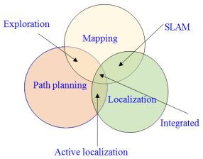
Figure 1. A task to be performed by a fully autonomous robot.
Many SLAM algorithms are implemented in ROS library packages, such as mapping, Hector SLAM, and Cartographer, which work well with portable platforms and limited computational resources
| [9] | Sobczak, Ł., Filus, K., Domańska, J. et al. "Finding the best hardware configuration for 2D SLAM in indoor environments via simulation based on Google Cartographer," Sci Rep 12, no. 18815 (2022), https://doi.org/10.1038/s41598-022-22938-y |
[9]
. In this paper, to be a fully autonomous robot, one must perform tasks, such as mapping, localization, and path planning, as depicted in
Figure 1. As previously described, SLAM is a technique that not only creates a map of an unknown area but also determines the robot's location within that map. After the SLAM process, path planning is defined. Only if the map of the environment is generated can a robot plan a path autonomously.
2. Framework of Software for Autonomous Mobile Robot
2.1. Robot Operating System
The Robot Operating System
is an open-source robot operating system software framework designed for developing applications that can be run on robotic hardware. It offers functionalities such as package management, communication between processes, and hardware abstraction.
The principal components of ROS include:
a. Roscore: this is the main process responsible for managing all of the ROS (Robot Operating System) systems.
b. Nodes: this is an executable that interacts with other nodes via ROS. They aid in the control of various functions.
c. Messages: its bits of information that nodes use to communicate with one another. Node communicates via messages.
d. Messages in ROS are transmitted via Topics.
Nodes can simultaneously send multiple messages to a topic and subscribe to a topic to receive messages. Typically, these nodes are used to process raw sensory information, such as that, from a lidar, motor encoders, distance sensors, etc. After processing the sensory information according to the needs of the desired application, it is published to a ROS topic in the form of messages. The ROS framework was selected because, in addition to facilitating straightforward sensor integration, it also includes many of the essential features, such as robotic control and SLAM algorithms. ROS allows for the easy utilization of software written in Python or C++. Furthermore, as the high-level control of the indoor autonomous mobile robot is implemented in ROS, this paper is built on the ROS platform.
2.2. Gazebo
The Gazebo
is a ROS-integrated simulation program that provides a 3D dynamic simulator of the real world. The latter allows us to test the activity of our robot efficiently in a complex dynamic and static indoor environment. The gazebo is commonly used to evaluate robotics algorithms and robot designs, as well as to test their execution in real-world scenarios. Gazebo allows a user to create complex environments and simulate the robot in those environments. In Gazebo, the user can create a three-dimensional model of the robot and incorporate sensors. It is the simulation environment that offers various ROS APIs, allowing users to model robots and gather sensor data. A real-world environment can be easily constructed in Gazebo. It allows the user to manipulate the properties of the environment over ROS, as well as spawn and introspect on the state of models in the environment, by using the ROS API (Application Programming Interface). Several objects were randomly placed in this environment where the map was created along with the objects, as these objects were considered static obstacles. In the Gazebo, an indoor environment map is created for the robot to move and map accordingly.
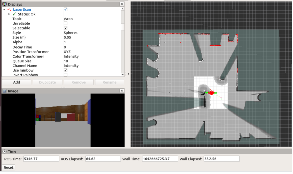
2.3. Rviz
Rviz is a 3D visualization application that makes it easy to view data from high-resolution cameras, 3D lasers, and Kinect sensors. Rviz, in a nutshell, allows us to visualize the sensors and their output in a simulated environment. Rviz is serves as a 3D visualization tool for displaying sensor information and the state of ROS. As create a map based on the laser scan data and use it for auto navigation. As access and graphically represent values in Rviz by using camera images, laser scans, and so on. In Rviz, coordinates are referred to as frames. We can choose from various displays to view in Rviz; they are data from various sensors. We can give any data to be displayed in Rviz by clicking the add button. The grid display will provide the ground or reference. The laser scanner display will show the results of the laser scanners. Sensor msgs/Laser scans display will be used for laser scans. The program's position will be displayed in the point cloud display. The reference point will be displayed on the axes display. The Rviz simulation is depicted in
Figure 2. Figure 2. RVIZ simulation.
3. Methods of Mapping Localizing & Path Planning
3.1. Cartographer Algorithm
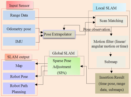
Cartographer is a system that offers real-time and an open-source package for 2D and 3D graph-based Simultaneous localization and mapping that integrates seamlessly with the Robot Operating System (ROS). It generates both a 2D occupancy grid map and a 3D point cloud map. The reusability of such an algorithm is dependent upon platform and sensor configurations. Cartographer algorithms can consist of two distinct linked subsystems. The first subsystem is known as Local SLAM. Which serves as the front end of Cartographer's. To generate sub-maps the Local SLAM gathers data and information from range sensors and other proprioceptive sensors including RPLIDAR A1, IMU, and wheel encoders to provide scaled-down representations of a portion of the map that an accurate overview of a specific area. The second subsystem is known as Global SLAM. Which serves as the back end of Cartographer. This subsystem focuses on the sole purpose of finding loop closure constraints. In this process, a constraint-based weight parameter is added to Local SLAM, and parameters in Global SLAM are tuned to optimize loop closure detection. Detailed methods are depicted in
Figure 3.
Figure 3. An Overview of the Cartographer Method.
In the Local SLAM, multiple scan-matching is performed against these recent sub-maps to accumulate pose estimation errors. Regular pose optimization is implemented to prevent the errors from accumulating. When a submap is completed, no additional laser scans are incorporated, and all completed sub-maps contribute to scan matching for loop closure (i.e., revisiting the same location on the map)
To find a laser scan, the scan matcher iterates automatically and systematically through the completed sub-maps. If a reasonably good match is found within a search window based on an estimated position in the sub-maps, it is included as a loop closure constraint in the optimization problem. Consequently, solving this optimization issue aids in immediately closing the loop when a location is encountered. The Cartographer's motion filter helps in down-sampling the raw points hit by the laser into fixed-size cubes while retaining the centroid of each cube. The cartographer utilizes an adaptive voxel filter as well. This filter seeks to determine the optimal voxel size (within a specified maximum width) to achieve a given number of points. The pose extrapolator block merges data from the other sensors, as well as the range finder, to predict where the next scan should be added to the submap. To avoid excessive scan insertions, it passes through the motion filter block to check if motion is detected between two scans. In the Global SLAM, the sparse pose adjustment (SPA) block runs and operates in the background, rearranging sub-maps to create a cohesive global map. At a higher level of abstraction, it can be summarized that the main function of Local SLAM is to generate excellent sub-maps, while the function of Global SLAM is to effectively bind these sub-maps together.
3.2. Localization Method of Adaptive Monte Carlo Localization
Monte Carlo Localization (MCL) is a widely utilized algorithm in robotics that employs a particle filter for determining the localization (position and orientation) of a robot. Localization entails estimating the robot's position and orientation, collectively known as its pose, as it moves and senses its surroundings. In localization, each particle has its unique map of the environment as well as offers a potential estimate of the robot's location, i.e. to estimate where the robot is. The algorithm typically initiates with a random distribution of particles across the pose space. When the robot moves, the particle shifts and attempts to predict its update. When the robot detects a recognizable feature, the weights of the particles surrounding that feature increase according to a Gaussian distribution pattern. Upon movement of the robot, the particles are re-sampled with equal weights in accordance with recursive Bayesian estimation, ensuring that, the number of particles in the areas where the previous belief was high is greater than in the rest of the space. This process continues until the particles converge around the robot's actual pose. In this manner, the performance of each particle can be observed, and more particles from that neighborhood can be drawn when necessary. To maintain a consistent particle count, resampling is employed. However, because the correlation score for each particle must be calculated iteratively, this localization method is computationally intensive. As a result, increasing the number of particles eventually increases computation time, while decreasing the number of particles may lead to poor localization. To enhance this type of localization, Adaptive Monte Carlo Localization (AMCL)
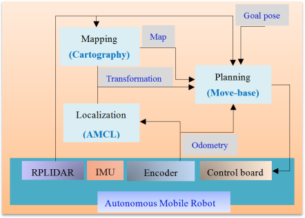
has emerged, which optimizes MCL by adaptively sampling the particles based on error estimates using the Kullback-Leibler divergence (KLD) and is increasingly employed to improve such a form of localization. It regulates the quantity of particles based on the odometry and the differences in particle-based position. The detail is shown in
Figure 4.
Figure 4. The software architecture of the method of three main modules i.e. mapping, localization, and planning.
4. Experimental Results
Mapping, localizing, and planning routes for autonomous mobile robots in indoor settings have been tested in simulated environments built on the simulation software and implementing the autonomous mobile robot. The experiments were carried out in unstructured indoor environments in different scenarios. The gazebo was used as a simulator for creating the simulation environments due to its capability to efficiently and accurately simulate a wide range of robots in complex indoor environments. The experimental findings for the autonomous mobile robots operating in indoor environments, where mapping, localization, and path planning are performed within the Gazebo simulator.
Figure 6 shows the mapping process using the Gazebo simulation environments for autonomous mobile robots, while
Figure 7 shows Rviz visualization results for the localization process, and
Figure 8 shows the path planning process. During the experiments in the Gazebo Simulator, an RPLIDAR scanner is used to create a global map of a given environment and estimate the autonomous mobile robot pose within the map, as well as path planning.
The mapping process depicted in
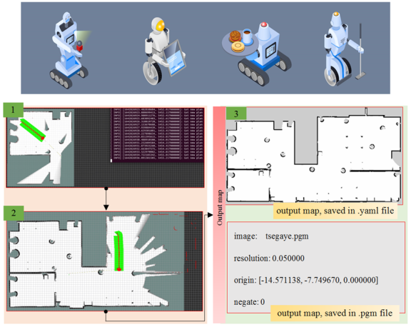
Figure 6, shows the process of mapping in ROS, during mapping by giving goal points the robot moves the same wise to make a map autonomously and saves by using a map saver as yaml and pgm file in the ROS. Pose, orientation, and localization are all part of the process of localization. In
Figure 6 (no:1, no:2) Simulation in Rviz, the black dots and line represent obstacles through which the mobile robot cannot pass; the white area represents a local cost map for obstacle avoidance with static and dynamic objects; In the map, the robot is red color and the green axes represent the mobile robot's current pose; that is, x-y-z axes; its particles used by the AMCL algorithm to estimate the mobile robot's pose.
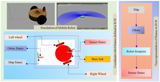
Figure 6 (no:3) shows the saved map and pgm/yaml information. The autonomous mobile robot system can have multiple broadcasters, with each one conveying information a distinct component of the robot of the robot. The different coordinate frames defined in ROS and utilized in this paper: The first is Robot footprint: - This frame, referred to as the "robot's frame." is securely fastened at the center of the mobile base, positioned between the two wheels. The sensor is linked to the base link. This frame helps easily visualize the robot's location on a given map. The second is Odom: - The Odom frame is the frame that is located at the starting point of the robot's movement. The third is Map: - The map frame, like the Odom frame, the map frame serves as a reference. However, with the only difference being that the pose of the robot, relative to the map frame remains relatively stable over time, unlike the odom frame. This frame is where the SLAM (Simultaneous Localization and Mapping) process occurs. The fourth is sensor frame: - These frames are primarily defined by the type of sensors. The detail of the autonomous mobile robot and tree representation of coordinate frames defined in the robot operating system are depicted in
Figure 5. Figure 5. Coordinate Robot and Tree representation of frames defined in ROS.
Various applications of indoor autonomous mobile robots, including servicing in hotels, helping disabled people, cleaning, and more.
Figure 6. Mapping Process.
Figure 7. Localization process.
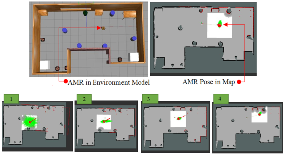
The simulation results of the AMCL in Ros are shown in
Figure 7, in which number (1) shows particles cloud-dense because of high uncertainty, number (2) and number (3) show particle alignment once the AMR starts moving and number (4) shows that particles converged in a stable state.
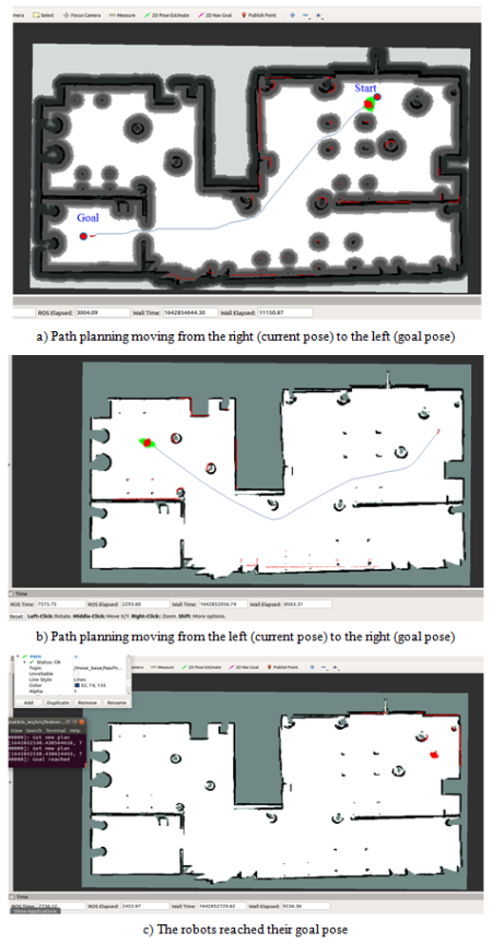
The planning module is mainly built on the move-based ROS package, which is a critical component of the navigation stack. The move base package includes a ROS interface for configuring, running, and interacting with the navigation stack, which consists of several inner components such as a global planner, local planner, global cost map, local cost map, and recovery behaviors. While such inner components are already implemented in the navigation stack, each robot platform requires the creation of components for a base controller, an odometry source, sensor sources, and sensor transforms. These components are created in this paper, using the Autonomous mobile robot and the RPLIDAR scanner. As a result, the package can easily implement the functions required for autonomous navigation. To build a local cost map for collision avoidance, generate collision-free trajectories to reach the goal pose, and generate control commands to follow the trajectories. The package requires five data inputs: raw laser range data, frame transform data, prebuilt map data, estimated current pose data of the mobile robot, and goal pose data. The mapping and localization modules provide the prebuilt map and the estimated current pose of the mobile robot, respectively. As shown in
Figure 8 (a), (b), (c), the mobile robot finally outputs trajectories and control commands (x, y, and θ velocities). The blue line extending from the mobile robot's current pose represents the global path to a given goal pose while avoiding obstacles, and the short and bright green line located beneath or next to the global path represents the local path to follow the global path.