Abstract
This study presents a transient numerical investigation of heat transfer and airflow characteristics in a semi-cylindrical solar air heater using COMSOL Multiphysics. A three-dimensional conjugate heat transfer model was developed to evaluate the effect of daily solar-radiation variation on air temperature, local convective heat transfer, Reynolds number, and useful heat gain. The model includes transient solar heat flux on the absorber surface, heat loss from the outer collector surface by natural convection, no-slip wall conditions, and a free outlet boundary condition. The calculation was performed for a low inlet-air velocity of 0.01 m/s during the period from 08: 00 to 18: 00. For the adopted geometry, the hydraulic diameter was 0.611 m, and the Reynolds number was approximately (3.7–4.0) × 102, indicating a laminar low-velocity regime. The maximum absorber-region temperature reached about 371–374 K during peak solar irradiation, while the maximum air temperature at the control points was about 338–340 K. The maximum local convective heat transfer coefficient and useful heat gain were approximately 0.176 W/(m2·K) and 2.3–2.4 W, respectively. The results show that the semi-cylindrical geometry forms a stable temperature field under low-velocity conditions. However, the useful heat output remains limited because of the small air mass flow rate. Therefore, the developed model should be considered as a baseline numerical tool for further optimization at higher airflow rates and for future experimental validation.
|
Published in
|
American Journal of Modern Energy (Volume 12, Issue 2)
|
|
DOI
|
10.11648/j.ajme.20261202.11
|
|
Page(s)
|
25-34 |
|
Creative Commons
|

This is an Open Access article, distributed under the terms of the Creative Commons Attribution 4.0 International License (http://creativecommons.org/licenses/by/4.0/), which permits unrestricted use, distribution and reproduction in any medium or format, provided the original work is properly cited.
|
|
Copyright
|
Copyright © The Author(s), 2026. Published by Science Publishing Group
|
Keywords
Semi-cylindrical Solar Air Heater, Numerical Modeling, Heat Transfer, Airflow, Convective Heat Transfer Coefficient,
Useful Heat Gain, Solar Air Collector, COMSOL Multiphysics
1. Introduction
Energy is a key factor in industrial development and economic growth. However, dependence on limited fossil fuel resources has increased environmental pollution and disturbed natural ecological balance. In this context, renewable energy plays an important role in sustainable development by reducing greenhouse gas emissions, improving energy security, supporting technological progress, creating jobs, and strengthening environmental and economic stability
| [1] | Jaiswal K. K., Chowdhury C. R., Yadav D., Verma R., Dutta S., Jaiswal K. S., Sangmesh B., Karuppasamy K. S. K. Renewable and sustainable clean energy development and impact on social, economic, and environmental health // Energy Nexus. 2022. Vol. 7. Article 100118.
https://doi.org/10.1016/j.nexus.2022.100118 |
[1]
.
Solar air heaters are a promising renewable energy technology. They convert solar radiation into thermal energy of an air stream and can reduce environmental impact. Compared with other solar energy systems, they have several advantages, including low initial cost, simple design, limited need for automation, and low operating expenses
| [2] | Alaiwi Y., Ahmed T. Solar air heaters classifications and enhancement: a review // Babylonian Journal of Mechanical Engineering. 2024. Vol. 2024. P. 71-80.
https://doi.org/10.58496/BJME/2024/009 |
[2]
. However, conventional flat-plate solar air heaters usually have relatively low efficiency. This is mainly due to the low heat capacity of air and weak convective heat transfer between the absorber plate and the circulating airflow inside the channel
| [3] | Singh V. P., Jain S., Karn A., Dwivedi G., Chaturvedi P. Recent developments and advancements in solar air heaters: a detailed review // Sustainability. 2022. Vol. 14. No. 19. Article 12149. https://doi.org/10.3390/su141912149 |
[3]
.
Over the last two decades, many methods have been studied to improve the thermal performance of solar air heaters. These methods include the use of ribs, baffles, fins, and other turbulence-generating elements to intensify convective heat transfer
| [4] | Chamarthi S., Singh S. A comprehensive review of experimental investigation procedures and thermal performance enhancement techniques of solar air heaters // International Journal of Energy Research. 2021. Vol. 45. No. 4. P. 5098-5164.
https://doi.org/10.1002/er.6255 |
[4]
. E. M. S. El-Said et al.
| [5] | Rajendran V., Vikram M. P., Kim S. C., Gullo P., Alodhayb A., Pandiaraj S., Prabakaran R. Enhancing the performance of a solar air heater by employing the broken V-shaped ribs // Environmental Science and Pollution Research. 2023. Vol. 30. No. 31. P. 77807-77818.
https://doi.org/10.1007/s11356-023-27814-4 |
[5]
investigated a tubular solar air heater with swirling flow, using a semi-cylindrical absorber plate with finned modules. They compared radial and longitudinal fins and found that radial fins provided better performance than longitudinal fins and smooth channels. The optimal configuration with five radial fins at a mass flow rate of 0.050 kg/s achieved thermal and thermohydraulic efficiencies of 76.79% and 72.40%, respectively. The Nusselt number reached 223.64, while the energy cost was 0.0105 USD/kWh.
Similarly, K. Nidhul et al.
| [6] | El-Said E. M. S., Abou Al-Sood M. M., Elsharkawy E. A., Abdelaziz G. B. Tubular solar air heater using finned semi-cylindrical absorber plate with swirl flow: experimental investigation // Solar Energy. 2022. Vol. 236. P. 879-897.
https://doi.org/10.1016/j.solener.2022.03.054 |
[6]
analyzed a solar air heater with semicircular side walls and W-shaped baffles using computational fluid dynamics. The study evaluated energy and exergy performance under turbulent flow conditions at Reynolds numbers from 5000 to 17500. The results showed that rounded channel corners reduced vortex formation while enhancing turbulence. The improved design increased the Nusselt number and friction factor by 3.24 and 4.03 times compared with a smooth channel. This led to increases in thermal and exergy efficiency of 40.7% and 95.4%, respectively. Overall, the semi-cylindrical solar air heater with W-shaped baffles showed better performance than conventional ribbed systems.
Semi-cylindrical geometry, especially when combined with internal ribs or baffles, can modify airflow structure, create local mixing zones, and intensify convective heat transfer
| [7] | Nidhul K., Yadav A. K., Anish S., Arunachala U. C. Efficient design of an artificially roughened solar air heater with semi-cylindrical side walls: CFD and exergy analysis // Solar Energy. 2020. Vol. 207. P. 289-304.
https://doi.org/10.1016/j.solener.2020.06.098 |
[7]
. Such designs improve airflow distribution, reduce temperature stratification, and increase the useful utilization of solar energy
| [8] | Chang Y., Xue Y., Geng G. Effect of the baffle’s type on thermal performance of solar air heaters // Case Studies in Thermal Engineering. 2024. Vol. 59. Article 104580.
https://doi.org/10.1016/j.csite.2024.104580 |
[8]
. A deeper understanding of the thermal and aerodynamic behavior of these systems is necessary for developing accurate calculation methods, optimizing design parameters, and predicting performance under different operating conditions. These improvements can also reduce exergy losses, increase economic feasibility, and expand the use of solar air heaters in sustainable energy technologies
| [9] | Bensaci C. E., Moummi A., Sanchez de la Flor F. J., Rodriguez Jara E. A., Rincon-Casado A., Ruiz-Pardo A. Numerical and experimental study of the heat transfer and hydraulic performance of solar air heaters with different baffle positions // Renewable Energy. 2020. Vol. 155. P. 1231-1244.
https://doi.org/10.1016/j.renene.2020.04.017 |
[9]
.
Despite extensive research on flat and rectangular-channel solar air heaters, detailed numerical studies of semi-cylindrical designs remain limited
| [10] | Kidane H., Farkas I., Buzás J. Role of computational fluid dynamics in solar air heating: a comprehensive overview of applications, benefits, and future directions // Journal of Thermal Analysis and Calorimetry. 2025. Vol. 150. No. 12. P. 8861-8877. https://doi.org/10.1007/s10973-025-14261-1 |
[10]
. Conventional systems still suffer from recirculation zones and weak convective mixing. Although ribs and finned elements are commonly used to improve performance, the specific advantages of semi-cylindrical channels under realistic solar radiation conditions have not yet been fully studied
| [11] | Abdukarimov B., Toxirov M., Jamshidov O., Mirzayev S. Mathematical modelling of heat and hydraulic processes in a solar air heater with a concave air duct absorber // E3S Web of Conferences. 2023. Vol. 452. Article 04007.
https://doi.org/10.1051/e3sconf/202345204007 |
[11]
.
This work addresses this research gap by numerically analyzing a semi-cylindrical solar air heater in COMSOL Multiphysics. The model allows coupled investigation of heat transfer and airflow processes
| [12] | Choi H. U., Moon K. A., Kim S. B., Choi K. H. CFD analysis of the heat transfer and fluid flow characteristics using the rectangular rib attached to the fin surface in a solar air heater // Sustainability. 2023. Vol. 15. No. 6. Article 5382.
https://doi.org/10.3390/su15065382 |
[12]
. The semi-cylindrical channel can reduce stagnant zones, improve airflow distribution, and enhance convective heat transfer, which is important for increasing collector thermal efficiency
| [13] | Zhu Q., Farkas I., Buzás J. Numerical study on the influence of baffle configuration on the thermal performance of solar air heaters // Results in Engineering. 2025. Vol. 27. Article 106913. https://doi.org/10.1016/j.rineng.2025.106913 |
[13]
. The obtained results can be used to develop calculation relationships and practical recommendations for optimizing solar air heaters used in low-temperature thermal processes, including space heating, agricultural drying, and ventilation air preheating.
2. Materials and Methods
2.1. Geometric Configuration
The solar air heater was modeled as a semi-cylindrical structure to provide more uniform heat distribution on the absorber surface and improve airflow behavior. The main semi-cylindrical collector chamber has a length of 3 m and a height of 0.3 m. In this model, the height of 0.3 m was considered as the geometric height of the semi-cylindrical profile, not as the radius of a full semicircle.
To ensure consistency in the absorber area calculation, an equivalent arc length of the cross-section was used. This gave an active heat-transfer surface area of 4.512 m². Thus, the absorber surface area was determined as the product of the collector length and the equivalent curved surface length. The value of 4.512 m² was treated as the equivalent active heat-transfer area used in the numerical model. It represents the curved absorber surface involved in heat transfer to the airflow and should not be interpreted as the simple geometric area of an ideal semicircle based only on the profile height.
A black-painted absorber surface was placed under the transparent glass cover to maximize solar energy absorption. The bottom and side walls of the structure were thermally insulated to reduce heat losses.
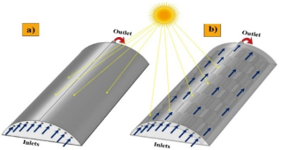
Air is supplied through 10 uniformly distributed inlet tubes with an internal diameter of 0.015 m, located in the lower part of the collector. The outlet pipe is placed on the opposite side of the chamber and has a diameter of 0.03 m. This configuration provides directed and stable airflow along the semi-cylindrical channel.
The total absorber surface area was taken as 4.512 m², and the hydraulic diameter of the flow channel was 0.611 m. To ensure reproducibility of the numerical model, the main boundary conditions used in the simulation are presented in
Table 1.
Table 1. Main boundary conditions of the numerical model.
Model domain / boundary | Boundary condition | Value or calculation form |
Inlet pipes | Inlet air velocity | v = 0.01 m/s |
Inlet air temperature | Time-dependent inlet air temperature | Tin = Tin(t) |
Outlet pipe | Free outlet condition | p = 0 Pa relative to atmospheric pressure |
Absorber surface | Transient heat flux from solar radiation | q″abs(t) = G(t) · τ · α |
Outer collector surface | Heat loss due to natural convection | q″loss = hext · (Ts − Tamb) |
Bottom and side walls | Thermal insulation | q″ = 0 |
Internal solid channel walls | No-slip condition for airflow | u = 0 |
Air-solid surface contact | Conjugate heat transfer between walls and airflow | Continuity of temperature and heat flux |
Initial condition | Initial temperature of the computational domain | T0 = Tamb at 08: 00 |
Here, G(t) is the time-dependent solar radiation intensity; τ is the transmittance of the transparent cover; α is the absorptance of the absorber surface; hext is the external natural convection coefficient, W/(m²·K); Ts is the outer collector surface temperature, K; and Tamb is the ambient temperature, K.
The model used the thermophysical properties of air, the transparent cover, the metal absorber, and the insulation layer. For air, density, dynamic viscosity, thermal conductivity, and specific heat capacity at constant pressure were defined. For the transparent cover, thermal conductivity and heat capacity were considered. For the metal absorber, high thermal conductivity was assigned to ensure heat transfer to the airflow. The insulation layer was modeled as a low-conductivity material to reduce heat losses through the bottom and side surfaces of the collector.
Figure 1. a) Geometric view of the semi-cylindrical solar air collector; b) Geometric view of the semi-cylindrical solar air collector showing the internal structure.
The 3D geometric model was developed in COMSOL Multiphysics to accurately represent the semi-cylindrical collector and its system of multiple inlet pipes and one outlet pipe. This design improves airflow distribution, increases solar energy utilization, and reduces temperature stratification inside the collector.
2.2. Finite Element Method Solver
The numerical study was carried out using the finite element method (FEM), which is a reliable tool for solving complex fluid flow and heat transfer problems. In the three-dimensional computational domain representing the solar air heater, the continuity, momentum, and energy equations were discretized and solved using FEM.
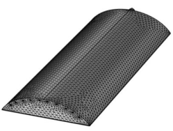
Figure 2. Generated computational mesh for the calculation domains.
To model boundary-layer effects and heat transfer more accurately, a computational mesh with local element refinement was generated near the baffles and absorber surface. This made it possible to describe velocity and temperature variations more correctly in the near-wall regions, where the main flow and thermal gradients are formed.
A segregated solution approach was used, in which the velocity, pressure, and temperature fields were iteratively refined until convergence was achieved. Spatial discretization was performed using the finite element formulation in COMSOL Multiphysics, allowing conjugate heat transfer between the solid structural elements and the airflow to be considered.
The detailed mesh parameters used in the finite element model are presented in
Table 2.
Table 2. Mesh parameters used in the finite element model.
Parameter | Value |
Mesh element type | Tetrahedral elements |
Number of elements | 1,412,237 |
Number of mesh nodes | 301,240 |
The generated mesh contained 1,412,237 tetrahedral elements and 301,240 nodes. This mesh was selected as the baseline computational grid because it provides local refinement near the inlet pipes, outlet channel, absorber surface, and internal baffles, where the highest velocity and temperature gradients are expected. The adopted mesh is sufficient for describing the main temperature-field and airflow-distribution trends in the semi-cylindrical channel. However, since a separate mesh-independence study was not performed in this work, the obtained results should be interpreted as baseline numerical predictions. In future work, coarse, medium, and fine meshes should be compared using outlet air temperature, maximum convective heat transfer coefficient, and useful heat gain as control parameters.
The mesh was refined in regions with expected high velocity and temperature gradients, including the inlet pipes, outlet channel, absorber surface, and internal baffles. This local refinement improves the accuracy of velocity and temperature field prediction and increases the reliability of heat transfer analysis inside the collector
| [14] | Hedau A., Singal S. K. Numerical study of solar air heater with semi-cylindrical tube roughness // Heat Transfer Enhancement Techniques: Thermal Performance, Optimization and Applications. Hoboken: Wiley, 2024. P. 233-250.
https://doi.org/10.1002/9781394270996.ch10 |
[14]
.
3. Equations and Mathematical Model
Heat distribution inside a solar air collector is a complex physical process that requires the coupled solution of several differential equations. Heat transfer in solid parts is described by the heat conduction equation, while airflow is governed by the Navier-Stokes equations. Therefore, the main governing equations and energy balance relations are used for a complete analysis of airflow and heat transfer processes
| [15] | COMSOL Multiphysics® v. 6.4. COMSOL AB, Stockholm, Sweden. Available at: www.comsol.com |
[15]
.
In this study, the thermohydraulic characteristics of the semi-cylindrical solar air heater were modeled in COMSOL Multiphysics. The main governing equations and required mathematical relations were introduced into the model as user-defined variables and calculation expressions
| [16] | Nidhul K., Yadav A. K., Anish S., Arunachala U. C. Thermo-hydraulic and exergetic performance of a cost-effective solar air heater: CFD and experimental study // Renewable Energy. 2022. Vol. 184. P. 627-641.
https://doi.org/10.1016/j.renene.2021.11.111 |
[16]
.
The heat conduction equation for solid bodies is written as follows:
(1)
Here, ρ is the material density, kg/m³; CD is the specific heat capacity at constant pressure, J/(kg·K); T is temperature, K; t is time, s; k is thermal conductivity, W/(m·K); Q is the volumetric heat source, W/m³; and Qrad is the radiation heat source term, W/m³.
This equation is used to determine the temperature and heat flux distribution in solid structural elements that are in thermal contact with each other. The motion of liquids and gases is mathematically described by the Navier-Stokes differential equations.
(2)
Here, Vₓ, Vᵧ, and Vz are the airflow velocity components in the corresponding coordinate directions; ρ is the fluid density; Fz is the body force related to gravity; ν is the molecular kinematic viscosity of the fluid or gas; and p is pressure.
The Navier-Stokes equations are used to determine the velocity and pressure distribution in the computational domain. The heat transfer equation for a moving liquid or gas medium is written as follows:
(3)
Equation (
3) is physically close to Equation (
1). The main difference is that, for a moving medium, the equation additionally includes a convective term related to the velocity of the liquid or gas flow.
The convective heat transfer coefficient, which characterizes the intensity of heat transfer between the heated surface and the airflow, is determined as follows:
Here, h is the convective heat transfer coefficient, W/(m²·K); Nu is the Nusselt number; k is the thermal conductivity of air, W/(m·K); and Dh is the hydraulic diameter, m.
For the semi-cylindrical flow channel, the hydraulic diameter was determined using the flow cross-sectional area and the wetted perimeter:
where Ac is the flow cross-sectional area of the air channel, and Pw is the wetted perimeter of the channel, m. For the adopted computational geometry, the hydraulic diameter was Dh = 0.611 m.
The Reynolds number was used to evaluate the airflow regime:
where ρ is the air density, v is the average airflow velocity, Dh is the hydraulic diameter of the channel, and μ is the dynamic viscosity of air.
The useful heat gain of the airflow was determined as follows:
where ṁ is the air mass flow rate, kg/s; CD is the specific heat capacity of air at constant pressure, J/(kg·K); and Tout and Tin are the outlet and inlet air temperatures of the collector, respectively.
The thermal efficiency of the collector was determined as follows:
where G is the solar radiation intensity, W/m², and Aₐ is the active absorber surface area, m².
4. Results and Discussion
COMSOL Multiphysics was used to analyze the thermal state and airflow behavior in the semi-cylindrical solar air heater under variable solar radiation and inlet air temperature from 08: 00 to 18: 00. The temperature fields in
Figures 3 and 4 are shown for selected time intervals from 08: 00 to 16: 00, while the parameters at control points T1, T2, and T3 were analyzed from 08: 00 to 18: 00.
The inlet air velocity was set to 0.01 m/s, and a transient heat flux was applied to the absorber surface to reproduce the daily variation of solar radiation intensity.
At Dh = 0.611 m, ρ ≈ 1.16-1.20 kg/m³, and μ ≈ 1.85 × 10⁻⁵ Pa·s, the calculated Reynolds number was approximately Re ≈ (3.7-4.0) × 10². This corresponds to a laminar low-velocity flow regime. Accordingly, the aerodynamic analysis in this study is limited to Reynolds-number-based flow regime identification and local airflow redistribution. Pressure drop, friction factor, and fan power were not evaluated in the present model and should be considered in future thermohydraulic optimization studies.
The airflow regime was evaluated using the Reynolds number. This made it possible to clarify the airflow behavior in the computational domain and correctly interpret changes in the convective heat transfer coefficient. Due to the low inlet velocity, the results were mainly analyzed in terms of local airflow redistribution and temperature field variation, rather than fully developed turbulent flow.
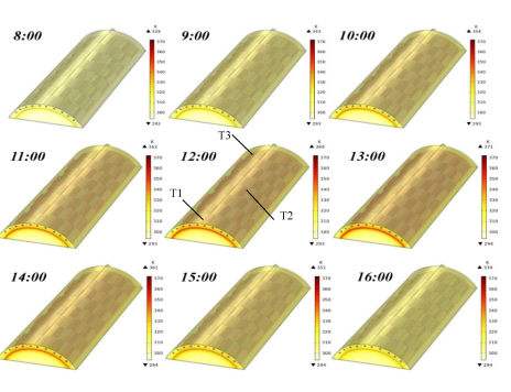
Figure 3. Temperature distribution in the solar air collector with the locations of control points T1, T2, and T3.
Heat losses from the collector to the environment were modeled as natural convection losses from the outer surfaces. This approach made the numerical model closer to real operating conditions and allowed the effects of variable solar radiation on temperature distribution, airflow velocity, and heat transfer efficiency inside the collector to be evaluated.
Figure 3 shows the temperature distribution in the solar air collector at different times of the day, from 08: 00 to 16: 00. The results show that as solar radiation increases, the absorber surface gradually heats up, raising the temperature inside the collector.
At 08: 00, the temperature field is relatively low, with about 328 K near the absorber surface. During the following hours, the temperature steadily increases to about 343 K at 09: 00 and 354 K at 10: 00. The maximum temperature occurs during peak solar activity, around 12: 00-13: 00, reaching approximately 371 K near the absorber surface.
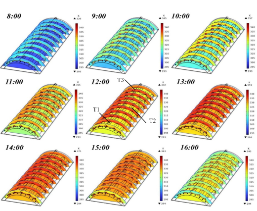
Figure 4. Cross-sectional temperature distribution in the solar air collector with the locations of control points T1, T2, and T3.
After 13: 00, the temperature gradually decreases due to the reduction in incoming solar energy. By 14: 00, the maximum temperature is about 361 K, and by 15: 00-16: 00, it decreases to approximately 351 K. Thus, the simulation confirms that the most intensive heating occurs around midday, while lower temperatures are observed in the morning and afternoon due to weaker solar radiation.
Figure 4 shows temperature distribution in the solar air collector at different times of the day as cross-sections of the computational domain. This visualization allows a more detailed assessment of airflow temperature changes inside the collector channel.
At 08: 00, the temperature inside the collector is relatively low, ranging from about 293 to 329 K, due to weak morning solar radiation. As solar radiation increases, the air temperature rises gradually, reaching about 345 K at 09: 00 and 357 K at 10: 00.
The highest temperature increase occurs from 11: 00 to 13: 00, when maximum values reach approximately 365-374 K. This period corresponds to the most favorable solar irradiation conditions, when the absorber transfers the greatest amount of heat to the airflow.
At 14: 00-15: 00, the temperature remains relatively high, about 363-371 K, indicating continued intensive heat transfer in the early afternoon. By 16: 00, the temperature decreases to around 340 K because of reduced solar heat flux.
The temperature cross-sections show that the airflow is heated quite uniformly while passing through the collector channel. Around midday, temperature gradients become more pronounced, confirming stronger heat transfer during peak solar activity. The results also show that the collector effectively increases air temperature during peak irradiation hours, while the later temperature decrease corresponds to the decline in solar radiation intensity.
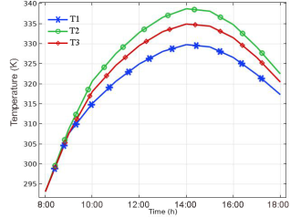
Figure 5. Air temperature variation at three control points.
Figure 5 shows the time-dependent air temperature inside the solar air collector at three control points, T1, T2, and T3, from 08: 00 to 18: 00. At all points, the temperature rises in the morning with increasing solar radiation, reaches its maximum around midday, and decreases in the afternoon as solar heat input declines.
The highest temperature is observed at T2, likely due to its favorable position near the heated absorber surface and local airflow distribution. At T3, the temperature is slightly lower but still reaches about 334 K. The lowest values are recorded at T1, where the maximum temperature is about 330 K. This difference is explained by non-uniform airflow and different heat transfer intensities in separate collector regions.
The results show that the most effective operating period is 11: 00-14: 00, when solar radiation is highest. They also indicate spatial non-uniformity of air heating inside the collector. This analysis is important for evaluating airflow uniformity, useful heat gain, and the overall thermal efficiency of the solar air collector.
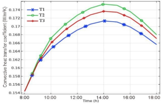
Figure 6. Convective heat transfer coefficients.
Figure 6 shows the variation of the convective heat transfer coefficient in the semi-cylindrical solar air heater at three control points, T1, T2, and T3, during the operating period from 08: 00 to 18: 00. The results show that the coefficient gradually increases in the morning due to higher solar radiation and stronger absorber heating. The maximum values occur around 13: 00-14: 00, after which the coefficient decreases as solar heat input declines.
The highest convective heat transfer coefficient is observed at T2, followed by T3, while T1 has the lowest values throughout the period. This indicates more favorable local heat transfer conditions in the central part of the collector. However, because of the low inlet air velocity, the absolute values of the coefficient remain low. Therefore, these results should be interpreted as characteristics of a low-velocity operating regime.
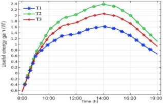
Figure 7. Useful heat gain of the airflow.
Figure 7 shows the time-dependent variation of useful heat gain in the airflow. Similar to the convective heat transfer coefficient, the useful heat output increases rapidly in the morning, reaches its maximum around midday, and then gradually decreases in the afternoon.
The highest useful heat gain is observed at approximately 14: 00 at point T2. It should be noted that the absolute values of Qᵤ remain low due to the low inlet air velocity. Therefore, the results mainly describe the distribution of the thermal effect inside the collector under a low-velocity regime, rather than the maximum energy performance of the system.
Point T1 again shows the lowest useful heat gain, while T3 has intermediate values. The negative values at 08: 00 indicate that, at the beginning of the simulation period, the air temperature inside the collector was lower than the inlet air temperature. As a result, short-term heat losses occurred before the absorber surface was sufficiently heated.
To summarize the results, the main calculated parameters at control points T1, T2, and T3 were combined into a comparative table.
Table 3. Main calculated parameters at control points T1, T2, and T3.
Indicator | T1 | T2 | T3 |
Maximum air temperature, K | ≈330 | ≈338-340 | ≈334 |
Time of maximum value | 13: 00-14: 00 | 13: 00-14: 00 | 13: 00-14: 00 |
Maximum heat transfer coefficient, W/(m²·K) | ≈0.172 | ≈0.176 | ≈0.174 |
Maximum useful heat gain, W | ≈1.6 | ≈2.3-2.4 | ≈2.0-2.1 |
The maximum air temperature was about 330 K at T1, 338-340 K at T2, and 334 K at T3. The highest convective heat transfer coefficient was observed at T2, confirming stronger local heat transfer in the central part of the collector. Under the selected low-velocity regime, the maximum useful heat gain was about 2.3–2.4 W, which corresponds to the very low air mass flow rate used in the simulation. Therefore, these values should be interpreted as the thermal response of the collector under a baseline low-flow numerical regime rather than as the maximum practical heat output of the system. At higher inlet velocities, the mass flow rate, Reynolds number, convective heat transfer, pressure losses, and total useful heat removal capacity would change significantly.
The main limitation of this study is that the simulation was performed only for one low inlet-air velocity. Therefore, the obtained results describe a laminar low-velocity operating regime and cannot be directly generalized to forced-flow industrial operation. In addition, experimental validation and full mesh-independence analysis were not included in the present stage of the study. Nevertheless, the numerical results provide a physically consistent baseline for evaluating daily temperature-field formation, local convective heat transfer, and useful heat gain in a semi-cylindrical solar air heater. Further research should include experimental validation, grid-independence testing, and simulations at higher inlet velocities to determine the optimal thermohydraulic operating range.
5. Conclusion
This study numerically analyzed heat transfer and airflow behavior in a semi-cylindrical solar air heater using COMSOL Multiphysics. A three-dimensional conjugate heat transfer model was developed to evaluate the daily variation of temperature distribution, Reynolds number, convective heat transfer coefficient, and useful heat gain under transient solar-radiation conditions.
For the adopted geometry, the active absorber surface area was 4.512 m² and the hydraulic diameter of the flow channel was 0.611 m. At the selected inlet air velocity of 0.01 m/s, the calculated Reynolds number was approximately (3.7–4.0) × 10², confirming a laminar low-velocity operating regime. The temperature field increased gradually from morning to midday and then decreased toward the evening as solar radiation declined. The maximum absorber-region temperature reached approximately 371–374 K during peak irradiation, while the maximum air temperature at the control points was about 338–340 K.
The highest local thermal response was observed at the middle control point T2. The maximum convective heat transfer coefficient reached approximately 0.176 W/(m²·K), and the maximum useful heat gain was about 2.3–2.4 W under the selected low-flow condition. These values confirm that the semi-cylindrical configuration forms a stable and spatially differentiated temperature field; however, the absolute useful heat output remains limited because of the very low air mass flow rate.
The results should therefore be interpreted as baseline numerical predictions for a low-velocity laminar regime rather than as the final practical performance of the collector. Future work should include mesh-independence testing, experimental validation, pressure-drop analysis, and simulations at higher airflow velocities to determine the optimal thermohydraulic operating conditions of the semi-cylindrical solar air heater.
Abbreviations
CFD | Computational Fluid Dynamics |
COMSOL | COMSOL Multiphysics |
FEM | Finite Element Method |
SAH | Solar Air Heater |
Re | Reynolds Number |
Nu | Nusselt Number |
Dh | Hydraulic Diameter |
Qu | Useful Heat Gain |
G | Solar Radiation Intensity |
Tin | Inlet Air Temperature |
Tout | Outlet Air Temperature |
Tamb | Ambient Temperature |
Ts | Surface Temperature |
hext | External Convective Heat Transfer Coefficient |
cp | Specific Heat Capacity at Constant Pressure |
Acknowledgments
The authors would like to thank Fergana State Technical University for academic and technical support during the preparation of this research. The authors also acknowledge the use of COMSOL Multiphysics for numerical simulation of heat transfer and airflow processes in the semi-cylindrical solar air heater.
Author Contributions
Sardorali Mirzayev: Data curation, Investigation, Resources, Software, Visualization
Bekzod Abdukarimov: Conceptualization, Formal Analysis, Investigation, Methodology, Writing – original draft
Mukhammadrafik Tokhirov: Supervision, Validation, Writing – review & editing
Conflicts of Interest
The authors declare no conflicts of interest.
References
| [1] |
Jaiswal K. K., Chowdhury C. R., Yadav D., Verma R., Dutta S., Jaiswal K. S., Sangmesh B., Karuppasamy K. S. K. Renewable and sustainable clean energy development and impact on social, economic, and environmental health // Energy Nexus. 2022. Vol. 7. Article 100118.
https://doi.org/10.1016/j.nexus.2022.100118
|
| [2] |
Alaiwi Y., Ahmed T. Solar air heaters classifications and enhancement: a review // Babylonian Journal of Mechanical Engineering. 2024. Vol. 2024. P. 71-80.
https://doi.org/10.58496/BJME/2024/009
|
| [3] |
Singh V. P., Jain S., Karn A., Dwivedi G., Chaturvedi P. Recent developments and advancements in solar air heaters: a detailed review // Sustainability. 2022. Vol. 14. No. 19. Article 12149.
https://doi.org/10.3390/su141912149
|
| [4] |
Chamarthi S., Singh S. A comprehensive review of experimental investigation procedures and thermal performance enhancement techniques of solar air heaters // International Journal of Energy Research. 2021. Vol. 45. No. 4. P. 5098-5164.
https://doi.org/10.1002/er.6255
|
| [5] |
Rajendran V., Vikram M. P., Kim S. C., Gullo P., Alodhayb A., Pandiaraj S., Prabakaran R. Enhancing the performance of a solar air heater by employing the broken V-shaped ribs // Environmental Science and Pollution Research. 2023. Vol. 30. No. 31. P. 77807-77818.
https://doi.org/10.1007/s11356-023-27814-4
|
| [6] |
El-Said E. M. S., Abou Al-Sood M. M., Elsharkawy E. A., Abdelaziz G. B. Tubular solar air heater using finned semi-cylindrical absorber plate with swirl flow: experimental investigation // Solar Energy. 2022. Vol. 236. P. 879-897.
https://doi.org/10.1016/j.solener.2022.03.054
|
| [7] |
Nidhul K., Yadav A. K., Anish S., Arunachala U. C. Efficient design of an artificially roughened solar air heater with semi-cylindrical side walls: CFD and exergy analysis // Solar Energy. 2020. Vol. 207. P. 289-304.
https://doi.org/10.1016/j.solener.2020.06.098
|
| [8] |
Chang Y., Xue Y., Geng G. Effect of the baffle’s type on thermal performance of solar air heaters // Case Studies in Thermal Engineering. 2024. Vol. 59. Article 104580.
https://doi.org/10.1016/j.csite.2024.104580
|
| [9] |
Bensaci C. E., Moummi A., Sanchez de la Flor F. J., Rodriguez Jara E. A., Rincon-Casado A., Ruiz-Pardo A. Numerical and experimental study of the heat transfer and hydraulic performance of solar air heaters with different baffle positions // Renewable Energy. 2020. Vol. 155. P. 1231-1244.
https://doi.org/10.1016/j.renene.2020.04.017
|
| [10] |
Kidane H., Farkas I., Buzás J. Role of computational fluid dynamics in solar air heating: a comprehensive overview of applications, benefits, and future directions // Journal of Thermal Analysis and Calorimetry. 2025. Vol. 150. No. 12. P. 8861-8877.
https://doi.org/10.1007/s10973-025-14261-1
|
| [11] |
Abdukarimov B., Toxirov M., Jamshidov O., Mirzayev S. Mathematical modelling of heat and hydraulic processes in a solar air heater with a concave air duct absorber // E3S Web of Conferences. 2023. Vol. 452. Article 04007.
https://doi.org/10.1051/e3sconf/202345204007
|
| [12] |
Choi H. U., Moon K. A., Kim S. B., Choi K. H. CFD analysis of the heat transfer and fluid flow characteristics using the rectangular rib attached to the fin surface in a solar air heater // Sustainability. 2023. Vol. 15. No. 6. Article 5382.
https://doi.org/10.3390/su15065382
|
| [13] |
Zhu Q., Farkas I., Buzás J. Numerical study on the influence of baffle configuration on the thermal performance of solar air heaters // Results in Engineering. 2025. Vol. 27. Article 106913.
https://doi.org/10.1016/j.rineng.2025.106913
|
| [14] |
Hedau A., Singal S. K. Numerical study of solar air heater with semi-cylindrical tube roughness // Heat Transfer Enhancement Techniques: Thermal Performance, Optimization and Applications. Hoboken: Wiley, 2024. P. 233-250.
https://doi.org/10.1002/9781394270996.ch10
|
| [15] |
COMSOL Multiphysics® v. 6.4. COMSOL AB, Stockholm, Sweden. Available at:
www.comsol.com
|
| [16] |
Nidhul K., Yadav A. K., Anish S., Arunachala U. C. Thermo-hydraulic and exergetic performance of a cost-effective solar air heater: CFD and experimental study // Renewable Energy. 2022. Vol. 184. P. 627-641.
https://doi.org/10.1016/j.renene.2021.11.111
|
Cite This Article
-
APA Style
Mirzayev, S., Abdukarimov, B., Tokhirov, M. (2026). Numerical Modeling of Heat Transfer and Aerodynamic Characteristics in a Semi-cylindrical Solar Air Heater. American Journal of Modern Energy, 12(2), 25-34. https://doi.org/10.11648/j.ajme.20261202.11
 Copy
|
Copy
|
 Download
ACS Style
Mirzayev, S.; Abdukarimov, B.; Tokhirov, M. Numerical Modeling of Heat Transfer and Aerodynamic Characteristics in a Semi-cylindrical Solar Air Heater. Am. J. Mod. Energy 2026, 12(2), 25-34. doi: 10.11648/j.ajme.20261202.11
Copy
|
Download
AMA Style
Mirzayev S, Abdukarimov B, Tokhirov M. Numerical Modeling of Heat Transfer and Aerodynamic Characteristics in a Semi-cylindrical Solar Air Heater. Am J Mod Energy. 2026;12(2):25-34. doi: 10.11648/j.ajme.20261202.11
Copy
|
Download
-
@article{10.11648/j.ajme.20261202.11,
  author = {Sardorali Mirzayev and Bekzod Abdukarimov and Mukhammadrafik Tokhirov},
  title = {Numerical Modeling of Heat Transfer and Aerodynamic Characteristics in a Semi-cylindrical Solar Air Heater},
  journal = {American Journal of Modern Energy},
  volume = {12},
  number = {2},
  pages = {25-34},
  doi = {10.11648/j.ajme.20261202.11},
  url = {https://doi.org/10.11648/j.ajme.20261202.11},
  eprint = {https://article.sciencepublishinggroup.com/pdf/10.11648.j.ajme.20261202.11},
  abstract = {This study presents a transient numerical investigation of heat transfer and airflow characteristics in a semi-cylindrical solar air heater using COMSOL Multiphysics. A three-dimensional conjugate heat transfer model was developed to evaluate the effect of daily solar-radiation variation on air temperature, local convective heat transfer, Reynolds number, and useful heat gain. The model includes transient solar heat flux on the absorber surface, heat loss from the outer collector surface by natural convection, no-slip wall conditions, and a free outlet boundary condition. The calculation was performed for a low inlet-air velocity of 0.01 m/s during the period from 08: 00 to 18: 00. For the adopted geometry, the hydraulic diameter was 0.611 m, and the Reynolds number was approximately (3.7–4.0) × 102, indicating a laminar low-velocity regime. The maximum absorber-region temperature reached about 371–374 K during peak solar irradiation, while the maximum air temperature at the control points was about 338–340 K. The maximum local convective heat transfer coefficient and useful heat gain were approximately 0.176 W/(m2·K) and 2.3–2.4 W, respectively. The results show that the semi-cylindrical geometry forms a stable temperature field under low-velocity conditions. However, the useful heat output remains limited because of the small air mass flow rate. Therefore, the developed model should be considered as a baseline numerical tool for further optimization at higher airflow rates and for future experimental validation.},
 year = {2026}
}
Copy
|
Download
-
TY  - JOUR
T1  - Numerical Modeling of Heat Transfer and Aerodynamic Characteristics in a Semi-cylindrical Solar Air Heater
AU  - Sardorali Mirzayev
AU  - Bekzod Abdukarimov
AU  - Mukhammadrafik Tokhirov
Y1  - 2026/06/10
PY  - 2026
N1  - https://doi.org/10.11648/j.ajme.20261202.11
DO  - 10.11648/j.ajme.20261202.11
T2  - American Journal of Modern Energy
JF  - American Journal of Modern Energy
JO  - American Journal of Modern Energy
SP  - 25
EP  - 34
PB  - Science Publishing Group
SN  - 2575-3797
UR  - https://doi.org/10.11648/j.ajme.20261202.11
AB  - This study presents a transient numerical investigation of heat transfer and airflow characteristics in a semi-cylindrical solar air heater using COMSOL Multiphysics. A three-dimensional conjugate heat transfer model was developed to evaluate the effect of daily solar-radiation variation on air temperature, local convective heat transfer, Reynolds number, and useful heat gain. The model includes transient solar heat flux on the absorber surface, heat loss from the outer collector surface by natural convection, no-slip wall conditions, and a free outlet boundary condition. The calculation was performed for a low inlet-air velocity of 0.01 m/s during the period from 08: 00 to 18: 00. For the adopted geometry, the hydraulic diameter was 0.611 m, and the Reynolds number was approximately (3.7–4.0) × 102, indicating a laminar low-velocity regime. The maximum absorber-region temperature reached about 371–374 K during peak solar irradiation, while the maximum air temperature at the control points was about 338–340 K. The maximum local convective heat transfer coefficient and useful heat gain were approximately 0.176 W/(m2·K) and 2.3–2.4 W, respectively. The results show that the semi-cylindrical geometry forms a stable temperature field under low-velocity conditions. However, the useful heat output remains limited because of the small air mass flow rate. Therefore, the developed model should be considered as a baseline numerical tool for further optimization at higher airflow rates and for future experimental validation.
VL  - 12
IS  - 2
ER  -
Copy
|
Download